PARKING ASSIST MONITOR SYSTEM Message indicating Back Door is Open is Displayed even after Back Door is Closed
DESCRIPTION
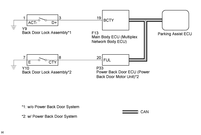
The parking assist ECU receives back door lock assembly open/close signals from the main body ECU (multiplex network body ECU) via CAN communication. When the back door is open, the camera aiming cannot be adjusted correctly because the rear television camera assembly is installed on the back door. Therefore, when adjusting the camera aiming calibration while the back door is open, a back door open warning message will be displayed on the screen and camera aiming adjustment will be canceled.
Tech Tips
-
The back door lock assembly is connected to the main body ECU (multiplex network body ECU) by the vehicle wire harness. (w/o power back door system)
-
The back door lock assembly is connected to the power back door ECU (power back door motor unit) by the vehicle wire harness. The power back door ECU (power back door motor unit) sends back door lock assembly signals to the main body ECU (multiplex network body ECU) via CAN communication. (w/ power back door system)
WIRING DIAGRAM
INSPECTION PROCEDURE
Note
-
When "System initializing" is displayed on the multi-display after the battery terminal disconnected, correct the steering angle neutral point Click here.
-
Depending on the parts that are replaced or operations that are performed during vehicle inspection or maintenance, calibration of other systems as well as the parking assist monitor system may be needed Click here.
PROCEDURE
-
READ VALUE USING INTELLIGENT TESTER
-
Connect the intelligent tester to the DLC3.
-
Turn the power switch on (IG).
-
Turn the intelligent tester on.
-
Enter the following menus: Body / Main Body / Data List.
-
Check the Data List for proper functioning of the following item.
Main Body (Main Body ECU (Multiplex Network Body ECU)) Tester Display Measurement Item/Range Normal Condition Diagnostic Note Back Door Courtesy SW Back door courtesy switch signal/ON or OFF ON: Back door open
OFF: Back door closed
- OK The back door courtesy switch functions as specified in the normal condition column.
NG 
CONFIRM MODEL Click here
OK 
REPLACE PARKING ASSIST ECU Click here
-
-
CONFIRM MODEL
-
Choose the model to be inspected.
Result Result Proceed to w/o power back door system A w/ power back door system B
B 
GO TO BACK DOOR CLOSER SYSTEM (DTC B2251) Click here
A 
-
-
CHECK HARNESS AND CONNECTOR (MAIN BODY ECU - BACK DOOR LOCK)
-
Disconnect the F13 connector from the main body ECU (multiplex network body ECU).
-
Disconnect the Y9 connector from the back door lock assembly.
-
Measure the resistance according to the value(s) in the table below.
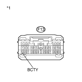
Standard Resistance Tester Connection Condition Specified Condition F13-19 (BCTY) - Body ground Always 10 kΩ or higher Y9-1 (ACT-) - Body ground Always Below 1 Ω F13-19 (BCTY) - Y9-3 (D+) Always Below 1 Ω Text in Illustration *1 Front view of wire harness connector
(to Main Body ECU (Multiplex Network Body ECU)
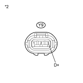
*2 Front view of wire harness connector
(to Back Door Lock Assembly)
NG
REPAIR OR REPLACE HARNESS OR CONNECTOR
OK
-
-
INSPECT BACK DOOR LOCK ASSEMBLY
-
Check the operation of the door lock motor.
-
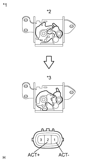
Text in Illustration *1 Component without harness connected
(Back Door Lock Assembly)
*2 Lock *3 Unlock Move the door lock to the lock position.
-
Apply battery voltage to the door lock motor and check the operation of the door lock motor.
Measurement Condition Specified Condition Battery positive (+) → 2 (ACT+)
Battery negative (-) → 1 (ACT-)
Unlocks
-
-
Check operation of the door courtesy switch.
-
Measure the resistance according to the value(s) in the table below.
Standard Resistance Measurement Condition Door Lock Condition Specified Condition 1 (ACT-) - 3 Locked 10 kΩ or higher 1 (ACT-) - 3 Unlocked Below 1 Ω
-
NG
REPLACE BACK DOOR LOCK ASSEMBLY Click here
OK
REPLACE MAIN BODY ECU (MULTIPLEX NETWORK BODY ECU)
-