LEXUS PARKING ASSIST-SENSOR SYSTEM Clearance Warning ECU Power Source Circuit
DESCRIPTION
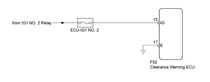
This circuit provides power to operate the clearance warning ECU.
WIRING DIAGRAM
INSPECTION PROCEDURE
PROCEDURE
-
CHECK HARNESS AND CONNECTOR (CLEARANCE WARNING ECU - BATTERY)
-
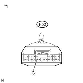
Text in Illustration *1 Front view of wire harness connector
(to Clearance Warning ECU)
Disconnect the F52 connector from the clearance warning ECU.
-
Measure the voltage according to the value(s) on the table below.
Standard Voltage Tester Connection Condition Specified Condition F52-15 (IG) - Body ground Power switch on (IG) 11 to 14 V F52-15 (IG) - Body ground Power switch off Below 1 V
NG 
REPAIR OR REPLACE HARNESS OR CONNECTOR
OK 
-
-
CHECK HARNESS AND CONNECTOR (CLEARANCE WARNING ECU - BODY GROUND)
-
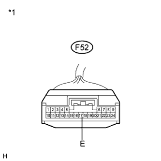
Text in Illustration *1 Front view of wire harness connector
(to Clearance Warning ECU)
Measure the resistance according to the value(s) in the table below.
Standard Resistance Tester Connection Condition Specified Condition F52-17 (E) - Body ground Always Below 1 Ω
NG
REPAIR OR REPLACE HARNESS OR CONNECTOR
OK 
PROCEED TO NEXT SUSPECTED AREA SHOWN IN PROBLEM SYMPTOMS TABLE Click here
-