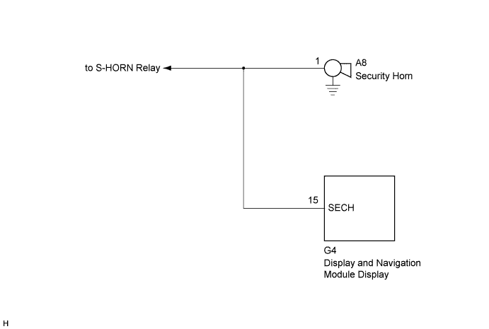
G-BOOK SYSTEM Security Horn Signal Circuit
WIRING DIAGRAM
INSPECTION PROCEDURE
Tech Tips
When replacing the display and navigation module display, perform the vehicle contract setting Click here.
PROCEDURE
-
CHECK HARNESS AND CONNECTOR (DISPLAY AND NAVIGATION MODULE DISPLAY - SECURITY HORN)
-
Disconnect the G4 display and navigation module display connector.
-
Disconnect the A8 security horn connector.
-
Measure the resistance according to the value(s) in the table below.
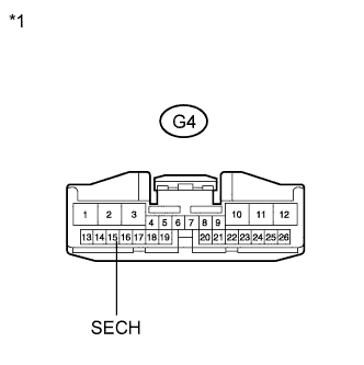
Standard Resistance Tester Connection Condition Specified Condition G4-15 (SECH) - A8-1 Always Below 1 Ω G4-15 (SECH) - Body ground Always 10 kΩ or higher Text in Illustration *1 Front view of wire harness connector
(to Display and Navigation Module Display)
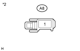
*2 Front view of wire harness connector
(to Security Horn)
NG 
REPAIR OR REPLACE HARNESS OR CONNECTOR
OK 
REPLACE DISPLAY AND NAVIGATION MODULE DISPLAY Click here
-