G-BOOK SYSTEM Emergency Call Switch Indicator Circuit
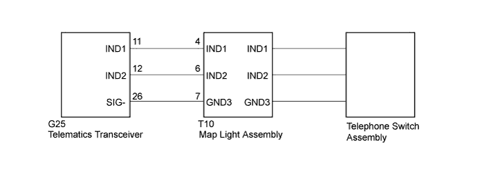
WIRING DIAGRAM
INSPECTION PROCEDURE
Tech Tips
When replacing the telematics transceiver, perform the vehicle contract setting Click here.
PROCEDURE
-
CHECK HARNESS AND CONNECTOR (TELEMATICS TRANSCEIVER - MAP LIGHT ASSEMBLY)
-
Disconnect the G25 telematics transceiver connector.
-
Disconnect the T10 map light assembly connector.
-
Measure the resistance according to the value(s) in the table below.
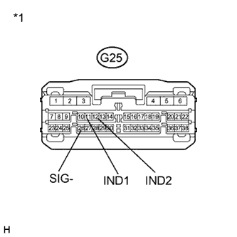
Standard Resistance Tester Connection Condition Specified Condition G25-11 (IND1) - T10-4 (IND1) Always Below 1 Ω G25-12 (IND2) - T10-6 (IND2) Always Below 1 Ω G25-26 (SIG-) - T10-7 (GND3) Always Below 1 Ω G25-11 (IND1) - Body ground Always 10 KΩ or higher G25-12 (IND2) - Body ground Always 10 KΩ or higher G25-26 (SIG-) - Body ground Always 10 KΩ or higher Text in Illustration *1 Front view of wire harness connector
(to Telematics Transceiver)
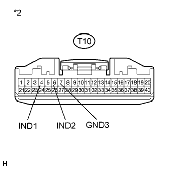
*2 Front view of wire harness connector
(to Map Light Assembly)
NG 
REPAIR OR REPLACE HARNESS OR CONNECTOR
OK 
-
-
INSPECT MAP LAMP ASSEMBLY
-
Disconnect the T10 map light assembly connector.
-
Connect 2 dry-cell batteries in series.
-
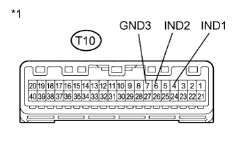
Text in Illustration *1 Component without harness connected
(Map Light Assembly)
Connect a positive (+) lead to terminal T10-4 (IND1) or T10-6 (IND2), and a negative (-) lead to terminal T10-7 (GND3) of the map light assembly connector.
-
Check if the illumination for the telephone switch assembly comes on.
OK The red indicator comes on when the positive (+) lead from the batteries is connected to terminal T10-4 (IND1) and the negative (-) lead is connected to terminal T10-7 (GND3). The green indicator comes on when the positive (+) lead from the batteries is connected to terminal T10-6 (IND2) and the negative (-) lead is connected to terminal T10-7 (GND3).
NG 
REPLACE TELEPHONE SWITCH ASSEMBLY Click here
OK 
REPLACE TELEMATICS TRANSCEIVER Click here
-
-
REPLACE TELEPHONE SWITCH ASSEMBLY
-
Replace the telephone switch assembly with a normal one and check if the same problem occurs again Click here.
OK The system returns to normal.
NG
REPLACE MAP LIGHT ASSEMBLY Click here
OK
END
-