G-BOOK SYSTEM Emergency Call Switch Illumination Circuit
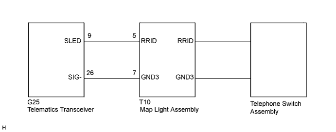
WIRING DIAGRAM
INSPECTION PROCEDURE
Tech Tips
When replacing the telematics transceiver, perform the vehicle contract setting Click here.
PROCEDURE
-
CHECK HARNESS AND CONNECTOR (TELEMATICS TRANSCEIVER - MAP LIGHT ASSEMBLY)
-
Disconnect the G25 telematics transceiver connector.
-
Disconnect the T10 map light assembly connector.
-
Measure the resistance according to the value(s) in the table below.
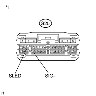
Standard Resistance Tester Connection Condition Specified Condition G25-9 (SLED) - T10-5 (RRID) Always Below 1 Ω G25-26 (SIG-) - T10-7 (GND3) Always Below 1 Ω G25-9 (SLED) - Body ground Always 10 kΩ or higher G25-26 (SIG-) - Body ground Always 10 kΩ or higher Text in Illustration *1 Front view of wire harness connector
(to Telematics Transceiver)
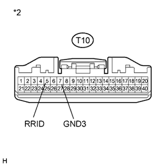
*2 Front view of wire harness connector
(to Map Light Assembly)
NG 
REPAIR OR REPLACE HARNESS OR CONNECTOR
OK 
-
-
INSPECT MAP LIGHT ASSEMBLY
-
Disconnect the T10 map light assembly connector.
-
Connect 4 1.5 V dry-cell batteries in series.
-
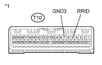
Text in Illustration *1 Component without harness connected
(Map Light Assembly)
Connect the positive (+) lead from the batteries to terminal T10-5 (RRID), and the negative (-) lead to terminal T10-7 (GND3) of the map light assembly connector.
-
Check if the illumination for the telephone switch assembly comes on.
OK Illumination for the telephone switch assembly comes on.
NG 
REPLACE TELEPHONE SWITCH ASSEMBLY Click here
OK 
REPLACE TELEMATICS TRANSCEIVER Click here
-
-
REPLACE TELEPHONE SWITCH ASSEMBLY
-
Replace the telephone switch assembly with a normal one and check if the same problem occurs again Click here.
OK The system returns to normal.
NG
REPLACE MAP LIGHT ASSEMBLY Click here
OK
END
-