G-BOOK SYSTEM, Diagnostic DTC:B15C5

| DTC Code | DTC Name |
|---|---|
| B15C5 | Manual Button Malfunction |
DESCRIPTION
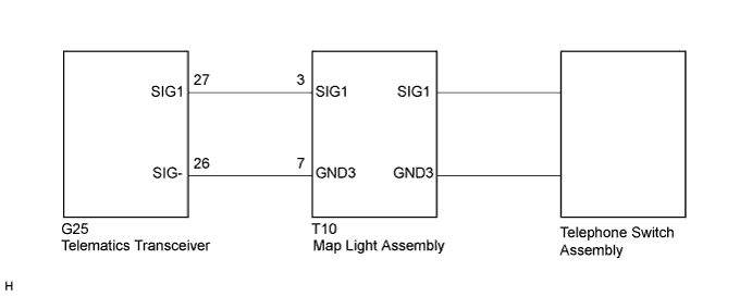
If the telematics transceiver detects an error in the communication between the telematics transceiver and the telephone switch assembly as a result of the telematics transceiver self check, this DTC will be stored.
| DTC No. | DTC Detection Condition | Trouble Area |
|---|---|---|
| B15C5 | A problem with the telephone switch assembly is detected. |
|
WIRING DIAGRAM
INSPECTION PROCEDURE
Tech Tips
When replacing the telematics transceiver, perform the vehicle contract setting Click here.
PROCEDURE
-
CLEAR DTC
-
Clear the DTC Click here.
NEXT 
-
-
CHECK DTC
-
Recheck for DTCs and check if the same DTC is output again Click here.
OK No DTCs are output.
NG 
INSPECT MAP LIGHT ASSEMBLY Click here
OK 
USE SIMULATION METHOD TO CHECK Click here
-
-
INSPECT MAP LIGHT ASSEMBLY
-
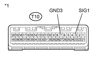
Text in Illustration *1 Component without harness connected
(Map Light Assembly)
Disconnect the T10 map light assembly connector.
-
Measure the resistance according to the value(s) in the table below.
Standard Resistance Tester Connection Condition Specified Condition T10-3 (SIG1) - T10-7 (GND3) Telephone switch assembly not operated 410 to 414 Ω T10-3 (SIG1) - T10-7 (GND3) Telephone switch assembly operated 81 to 83 Ω
NG
REPLACE TELEPHONE SWITCH ASSEMBLY Click here
OK
-
-
CHECK HARNESS AND CONNECTOR (TELEMATICS TRANSCEIVER - MAP LIGHT ASSEMBLY)
-
Disconnect the G25 telematics transceiver connector.
-
Disconnect the T10 map light assembly connector.
-
Measure the resistance according to the value(s) in the table below.
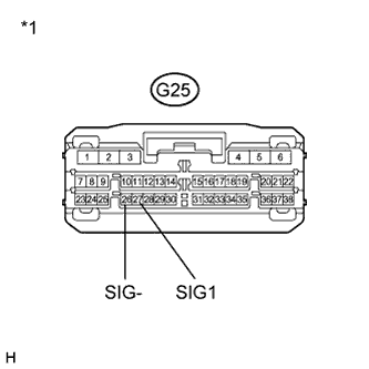
Standard Resistance Tester Connection Condition Specified Condition G25-27 (SIG1) - T10-3 (SIG1) Always Below 1 Ω G25-26 (SIG-) - T10-7 (GND3) Always Below 1 Ω G25-27 (SIG1) - Body ground Always 10 kΩ or higher G25-26 (SIG-) - Body ground Always 10 kΩ or higher Text in Illustration *1 Front view of wire harness connector
(to Telematics Transceiver)
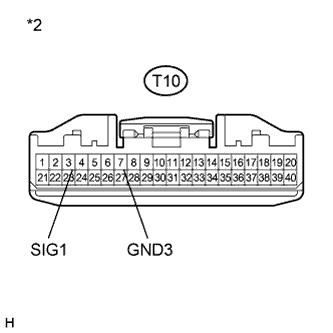
*2 Front view of wire harness connector
(to Map Light Assembly)
NG 
REPAIR OR REPLACE HARNESS OR CONNECTOR
OK
REPLACE TELEMATICS TRANSCEIVER Click here
-
-
REPLACE TELEPHONE SWITCH ASSEMBLY
-
Replace the telephone switch assembly with a normal one and check if the same problem occurs again Click here.
-
Clear the DTCs Click here.
-
Recheck for DTCs and check if the same DTC is output again.
OK No DTCs are output.
-
NG
REPLACE MAP LIGHT ASSEMBLY Click here
OK
END
-