HARD DISK DRIVE REMOVAL

-
PRECAUTION
Note
-
After the power switch is turned off, the display and navigation module display (HDD navigation system) records various types of memory and settings. As a result, after turning the power switch off, make sure to wait at least 60 seconds before disconnecting the cable from the negative (-) battery terminal.
-
A hard disk drive (HDD) is built into the navigation receiver assembly to store map data etc. which will be used for the navigation system. Therefore, make sure to read all of the precautions thoroughly before handling the navigation receiver assembly.
-
-
DISCONNECT CABLE FROM NEGATIVE BATTERY TERMINAL
Note
When disconnecting the cable, some systems need to be initialized after the cable is reconnected Click here.
-
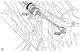
REMOVE SHIFT LEVER KNOB SUB-ASSEMBLY
-
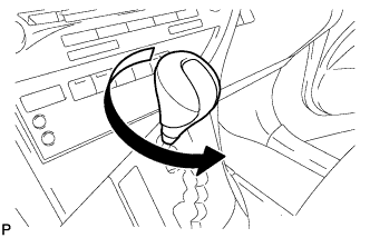
Turn the shift lever knob sub-assembly counterclockwise and remove the shift lever knob sub-assembly.
-
-
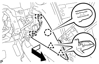
REMOVE UPPER CONSOLE PANEL SUB-ASSEMBLY
-
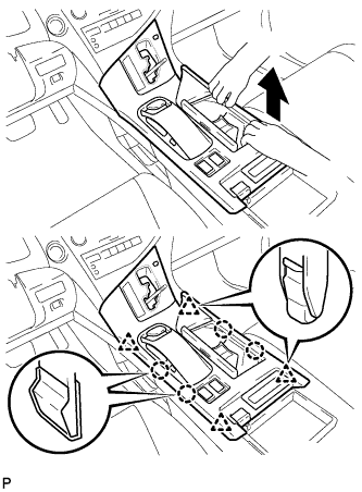
Move the shift lever to N.
-
Pull the upper console panel sub-assembly in the direction indicated by the arrow to disengage the 4 claws and 4 clips.
-
w/o Seat Heater System:
-
Disconnect the connector from the console box hole cover.
-
-
w/ Seat Heater System:
-
Disengage the 4 claws.
-
Disconnect the connector and remove the seat heater switch assembly.
-
-
Pull the upper console panel sub-assembly in the direction indicated by the arrow to disengage the 3 claws and 3 clips.
-
Disconnect each connector.
-
Disengage the clamp and remove the upper console panel sub-assembly.
-
-
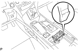
REMOVE NO. 2 CONSOLE BOX DUCT
-
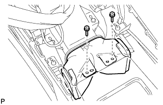
Remove the 2 screws and the No. 2 console box duct.
-
-
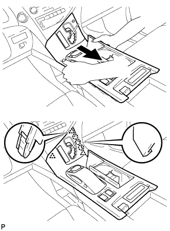
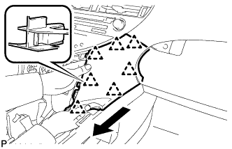
REMOVE CONSOLE REAR END PANEL SUB-ASSEMBLY
-
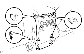
w/o Rear Seat Entertainment System:
-
Disengage the 4 claws and 6 clips, and remove the console rear end panel sub-assembly.
-
-
w/ Rear Seat Entertainment System:
-
Disengage the 4 claws and 6 clips.
-
Disconnect each connector and remove the console rear end panel sub-assembly.
-
-
-
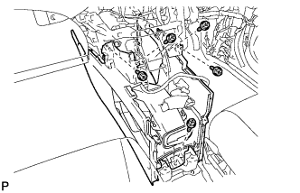
REMOVE MULTI-MEDIA INTERFACE ECU ASSEMBLY (w/ USB Audio System)
-
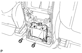
Remove the 2 bolts.
-
Disengage the clip and guide.
-
Disconnect the connector and remove the multi-media interface ECU assembly.
-
-
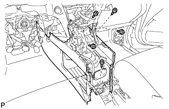
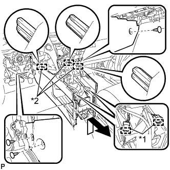
REMOVE REAR CONSOLE BOX ASSEMBLY
-
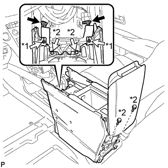
Text in Illustration *1 Screw *2 Bolt Disconnect each connector.
-
Remove the 2 screws and 4 bolts.
-
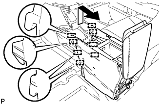
Pull the rear console box assembly in the direction indicated by the arrow to disengage the 8 guides and remove the rear console box assembly.
-
-
REMOVE INSTRUMENT PANEL GARNISH LH
-
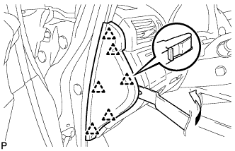
Using moulding remover B, disengage the 6 clips and remove the instrument panel garnish LH as shown in the illustration.
-
-
REMOVE NO. 1 SWITCH HOLE BASE
-
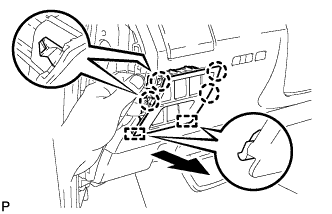
Push the No. 1 switch hole base in the direction indicated by the arrow to disengage the 4 claws and 2 guides.
-
Disconnect each connector and remove the No. 1 switch hole base.
-
-
REMOVE LOWER INSTRUMENT PANEL FINISH PANEL SUB-ASSEMBLY
-
Disengage the 2 claws and open the cover as shown in the illustration.
-

Remove the 2 screws <D>.
-
Disengage the 8 clips and 2 guides.
-
Disconnect each connector and remove the lower instrument panel finish panel sub-assembly.
-
-
REMOVE INSTRUMENT PANEL FINISH PANEL
-
Pull the instrument panel finish panel in the direction indicated by the arrow to disengage the claw, 2 clips and 2 guides, and remove the instrument panel finish panel.
-
-
REMOVE LOWER INSTRUMENT PANEL FINISH PANEL
-
Pull the lower instrument panel finish panel in the direction indicated by the arrow to disengage the 7 clips and remove the lower instrument panel finish panel.
-
-
REMOVE RADIO RECEIVER ASSEMBLY WITH REGISTER
Note
-
The 4 bolts of the radio receiver assembly with register are installed though the service holes at the bottom in the instrument panel. Make sure to check all of them.
-
If the radio receiver assembly with register is pulled without removing the 4 bolts, it may result in damage to the radio receiver assembly with register.
-
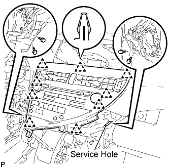
Remove the 4 bolts.
-
Disengage the 9 clips.
-
Disconnect each connector and remove the radio receiver assembly with register.
-
-
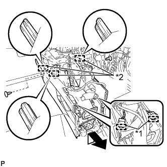
REMOVE CONSOLE BOX (for LHD)
-
Remove the 5 screws <D>.
-
Text in Illustration *1 Clamp *2 Guide Disengage the 2 clamps.
-
Remove the 3 clips.
-
Disengage the 3 guides and remove the console box as shown in the illustration.
-
-
REMOVE CONSOLE BOX (for RHD)
-
Remove the 5 screws <D>.
-
Text in Illustration *1 Clamp *2 Guide Disengage the 2 clamps.
-
Remove the 2 clips.
-
Disengage the 3 guides and remove the console box as shown in the illustration.
-
-
REMOVE SHIFT LEVER ASSEMBLY
-
Move the shift lever to N.
-
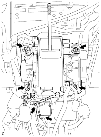
Disconnect the shift lock control ECU connector and transmission control switch wire connector.
-
Disconnect the 3 clamps.
-
Remove the 4 nuts and shift lever assembly.
-
Disconnect the end of the transmission control cable assembly from the shift lever assembly.
-
Turn the lock nut counterclockwise. While holding the lock nut, disconnect the transmission control cable from the shift lever retainer.
-
-
REMOVE DISPLAY AND NAVIGATION MODULE DISPLAY WITH BRACKET
-
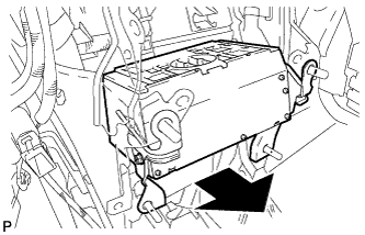
Pull out the display and navigation module display with bracket to the rear of the vehicle as shown in the illustration.
-
Disconnect each connector and remove the display and navigation module display with bracket.
-
-
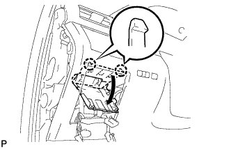
REMOVE HARD DISK DRIVE
-
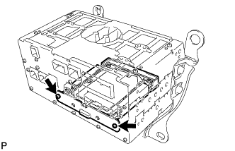
Remove the 2 screws.
-
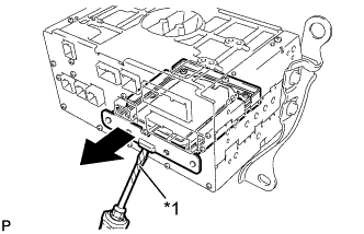
Text in Illustration *1 Protective Tape Using a screwdriver with its tip wrapped with protective tape, remove the hard disk drive as shown in the illustration.
-