NAVIGATION RECEIVER (for DVD) REMOVAL

-
EJECT MAP DISC
-
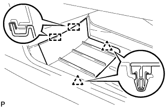
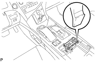
Disengage the 2 clips and 2 guides, and remove the front console box cover.
-
Turn the power switch on (ACC).
-
Push the "MENU" button on the remote operation controller.
-
Operate the remote operation controller and select "Info. Phone" on the navigation screen.
-
Operating the remote operation controller, select "Map Data" on the navigation screen.
-
Operating the remote operation controller, select "EJECT DVD" on the navigation screen to eject the map disc from the navigation receiver.
-
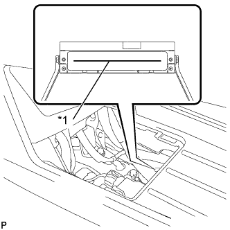
Text in Illustration *1 Disc Slot Remove the map disc from the navigation receiver.
-
Turn the power switch off.
-
-
REMOVE REAR DECK FLOOR BOX
-

Remove the 3 clips and the rear deck floor box.
-
-
DISCONNECT CABLE FROM NEGATIVE BATTERY TERMINAL
Note
When disconnecting the cable, some systems need to be initialized after the cable is reconnected Click here.
-
REMOVE SHIFT LEVER KNOB SUB-ASSEMBLY
-
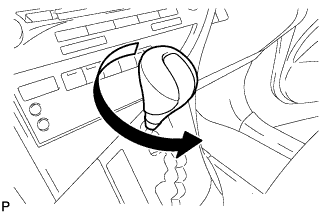
Turn the shift lever knob sub-assembly counterclockwise and remove the shift lever knob sub-assembly.
-
-
REMOVE UPPER CONSOLE PANEL SUB-ASSEMBLY
-
Move the shift lever to N.
-
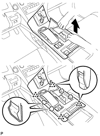
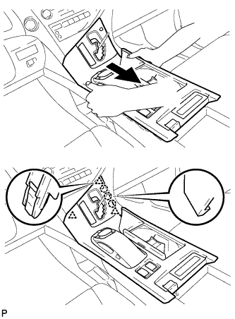
Pull the upper console panel sub-assembly in the direction indicated by the arrow to disengage the 4 claws and 4 clips.
-
w/o Seat Heater System:
-
Disconnect the connector from the console box hole cover.
-
-
w/ Seat Heater System:
-
Disengage the 4 claws.
-
Disconnect the connector and remove the seat heater switch assembly.
-
-
Pull the upper console panel sub-assembly in the direction indicated by the arrow to disengage the 3 claws and 3 clips.
-
Disconnect each connector.
-
Disengage the clamp and remove the upper console panel sub-assembly.
-
-
REMOVE NO. 2 CONSOLE BOX DUCT
-
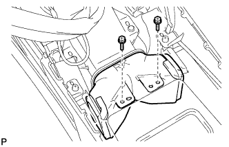
Remove the 2 screws and the No. 2 console box duct.
-
-
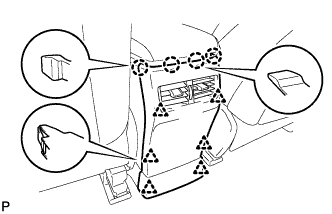
REMOVE CONSOLE REAR END PANEL SUB-ASSEMBLY
-
w/o Rear Seat Entertainment System:
-
Disengage the 4 claws and 6 clips, and remove the console rear end panel sub-assembly.
-
-
w/ Rear Seat Entertainment System:
-
Disengage the 4 claws and 6 clips.
-
Disconnect each connector and remove the console rear end panel sub-assembly.
-
-
-
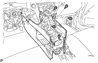
REMOVE MULTI-MEDIA INTERFACE ECU ASSEMBLY
-
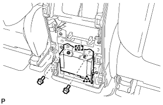
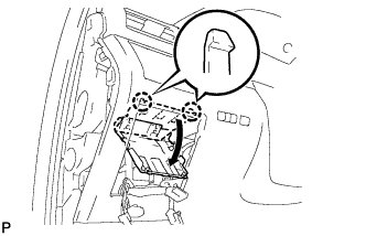
Remove the 2 bolts.
-
Disengage the clip and guide.
-
Disconnect the connector and remove the multi-media interface ECU assembly.
-
-
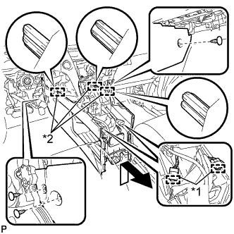
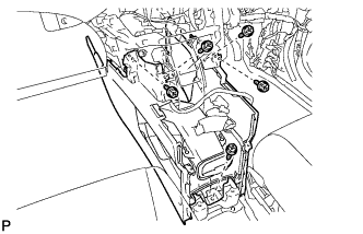
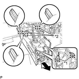
REMOVE REAR CONSOLE BOX ASSEMBLY
-
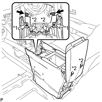
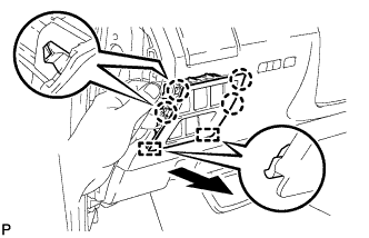
Text in Illustration *1 Screw *2 Bolt Disconnect each connector.
-
Remove the 2 screws and 4 bolts.
-
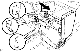
Pull the rear console box assembly in the direction indicated by the arrow to disengage the 8 guides and remove the rear console box assembly.
-
-
REMOVE INSTRUMENT PANEL GARNISH LH
-
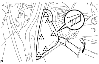
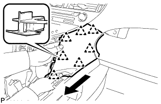
Using moulding remover B, disengage the 6 clips and remove the instrument panel garnish LH as shown in the illustration.
-
-
REMOVE NO. 1 SWITCH HOLE BASE
-
Push the No. 1 switch hole base in the direction indicated by the arrow to disengage the 4 claws and 2 guides.
-
Disconnect each connector and remove the No. 1 switch hole base.
-
-
REMOVE LOWER INSTRUMENT PANEL FINISH PANEL SUB-ASSEMBLY
-
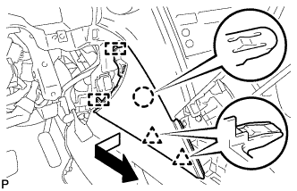
Disengage the 2 claws and open the cover as shown in the illustration.
-

Remove the 2 screws <D>.
-
Disengage the 8 clips and 2 guides.
-
Disconnect each connector and remove the lower instrument panel finish panel sub-assembly.
-
-
REMOVE INSTRUMENT PANEL FINISH PANEL
-
Pull the instrument panel finish panel in the direction indicated by the arrow to disengage the claw, 2 clips and 2 guides, and remove the instrument panel finish panel.
-
-
REMOVE LOWER INSTRUMENT PANEL FINISH PANEL
-
Pull the lower instrument panel finish panel in the direction indicated by the arrow to disengage the 7 clips and remove the lower instrument panel finish panel.
-
-
REMOVE RADIO RECEIVER ASSEMBLY WITH REGISTER
Note
-
The 4 bolts of the radio receiver assembly with register are installed though the service holes at the bottom in the instrument panel. Make sure to check all of them.
-
If the radio receiver assembly with register is pulled without removing the 4 bolts, it may result in damage to the radio receiver assembly with register.
-
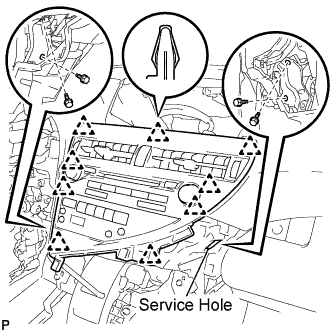
Remove the 4 bolts.
-
Disengage the 9 clips.
-
Disconnect each connector and remove the radio receiver assembly with register.
-
-
REMOVE FRONT CONSOLE BOX COVER
-
Using moulding remover A, disengage the 2 clips and 5 guides.
-
Disconnect the connector and remove the front console box cover.
-
-
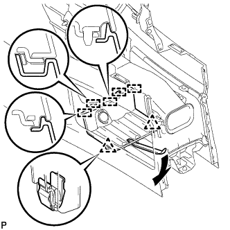
REMOVE CONSOLE BOX (for LHD)
-
Remove the 5 screws <D>.
-
Text in Illustration *1 Clamp *2 Guide Disengage the 2 clamps.
-
Remove the 3 clips.
-
Disengage the 3 guides and remove the console box as shown in the illustration.
-
-
REMOVE CONSOLE BOX (for RHD)
-
Remove the 5 screws <D>.
-
Text in Illustration *1 Clamp *2 Guide Disengage the 2 clamps.
-
Remove the 2 clips.
-
Disengage the 3 guides and remove the console box as shown in the illustration.
-
-
REMOVE SHIFT LEVER ASSEMBLY
-
Move the shift lever to N.
-
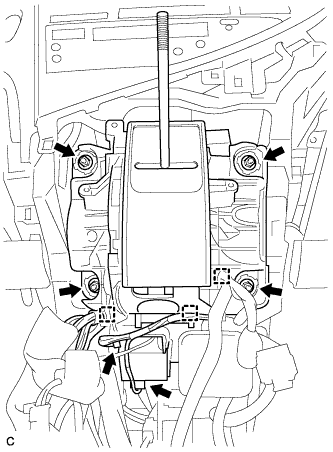
Disconnect the shift lock control ECU connector and transmission control switch wire connector.
-
Disconnect the 3 clamps.
-
Remove the 4 nuts and shift lever assembly.
-
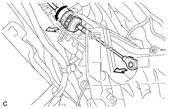
Disconnect the end of the transmission control cable assembly from the shift lever assembly.
-
Turn the lock nut counterclockwise. While holding the lock nut, disconnect the transmission control cable from the shift lever retainer.
-
-
REMOVE MULTI-MEDIA MODULE NAVIGATION ASSEMBLY WITH BRACKET
-
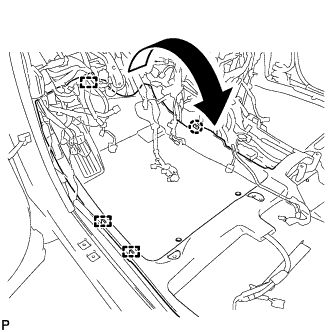
Disengage the 3 clamps.
-
Disengage the claw and turn back the floor carpet as shown in the illustration.
-
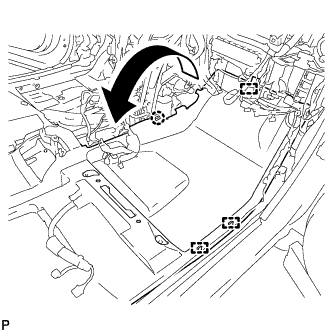
Disengage the 3 clamps.
-
Disengage the claw and turn back the floor carpet as shown in the illustration.
-
Disconnect the 2 connectors.
-
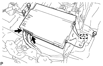
Remove the 3 bolts.
-
Disengage the guide and remove the multi-media module navigation assembly with bracket.
-
-
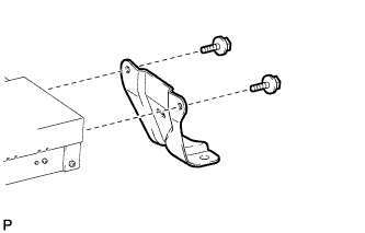
REMOVE NO. 1 DISC PLAYER BRACKET
-
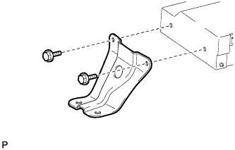
Remove the 2 bolts and No. 1 disc player bracket.
-
-
REMOVE NO. 2 DISC PLAYER BRACKET
-
Remove the 2 bolts and No. 2 disc player bracket.
-
-
REMOVE MULTI-MEDIA MODULE NAVIGATION ASSEMBLY
-
REMOVE DISPLAY AND NAVIGATION MODULE DISPLAY WITH BRACKET
-
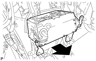
Pull out the display and navigation module display with bracket to the rear of the vehicle as shown in the illustration.
-
Disconnect each connector and remove the display and navigation module display with bracket.
-
-
REMOVE NO. 3 DISC PLAYER BRACKET
-
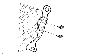
Remove the 2 bolts and No. 3 disc player bracket.
-
-
REMOVE NO. 4 DISC PLAYER BRACKET
-
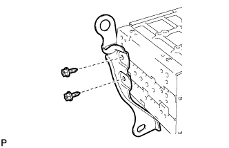
Remove the 2 bolts and No. 4 disc player bracket.
-
-
REMOVE DISPLAY AND NAVIGATION MODULE DISPLAY