G-BOOK SYSTEM SYSTEM DESCRIPTION

-
G-BOOK SYSTEM OUTLINE
-
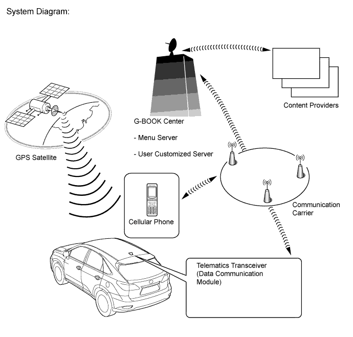
The G-BOOK system is a telematics service that links the vehicle and G-BOOK network (provides information from the G-BOOK center or content providers).
-
To use the G-BOOK system, it is necessary to connect the telematics transceiver (data communication module) to the display and navigation module display.
-
The user needs to follow the instructions on the multi-display to start using the G-BOOK system service after applying for the service at a dealership.
-
-
FUNCTION OF MAIN COMPONENTS
Component Function Telephone Switch Assembly When the telephone switch assembly is pressed, a switch signal is sent to the telematics transceiver.
(When a manual maintenance check or manual emergency call is performed.)
LED Indicator Light Green
-
Turns on for 5 seconds after the power switch is turned on (ACC).
-
Turns on when the system is under a service contract and operating normally.
-
Blinks during a call.
-
Blinks during a manual maintenance check.
-
Turns off when the system is malfunctioning.
Red
-
Turns on for 5 seconds after the power switch is turned on (ACC).
-
Turns on when the telematics transceiver is not within the service area.
-
Blinks when a call is made while the system is still malfunctioning.
-
Turns off when the system is operating normally.
-
Blinks when the mayday battery needs to be replaced.
-
Blinks when in diagnostic mode to indicate a DTC.
Telephone Microphone Assembly
-
When the operator service is used: Sends the microphone voice signal to the display and navigation module display.
-
When an emergency call is made: Sends the microphone voice signal to the telematics transceiver.
Telephone Antenna Assembly Sends and receives the data and voice signals used for the G-BOOK service through a communication network. Telematics Transceiver
-
Uses the telephone antenna assembly to send and receive the data and voice signals used for the G-BOOK service through a communication network.
-
When the operator service is used: Sends a received voice signal to the display and navigation module display.
-
When the operator service is used: Sends a sent voice signal from the display and navigation module display to the telephone antenna assembly.
-
When an emergency call is made: Sends a received voice signal to the vehicle speakers.
-
When an emergency call is made: Receives a sent voice signal from the telephone microphone assembly.
-
When an emergency call is made: Sends a mute signal to the stereo component amplifier assembly. (Mute function becomes active during the call.)
-
When an emergency call is made: Sends the location information to the G-BOOK center.
Mayday Battery (Back-up battery)
-
When automatic emergency call is performed, the mayday battery provides power to the DCM.
-
When a manual emergency call is made, the mayday battery is not used as the power source.
-
The mayday battery conducts a self-diagnosis every time the power switch is turned on (IG), and after an automatic emergency call or manual emergency call is made, and the result is sent to the DCM.
GPS Antenna Receives GPS radio waves and sends them to the display and navigation module display. Multiplex Network Body ECU (Main Body ECU) Sends a security horn sounding signal to the display and navigation module display when the theft deterrent system is activated. Display and Navigation Module Display
-
Sends and receives the data used for the G-BOOK service to and from the telematics transceiver using a telematics data signal.
-
When the operator service is used: Sends the sent voice signal from the telephone microphone assembly to the telematics transceiver.
-
When the operator service is used: Sends the received voice signal from the telematics transceiver to the stereo component amplifier assembly using a MOST signal.
-
Sends the vehicle location information to the telematics transceiver.
-
When a warning comes on, the display and navigation module display receives a warning ON signal from the combination meter assembly via CAN communication and the telematics transceiver sends it to the G-BOOK center.
-
When the theft deterrent system is activated, the telematics transceiver sends the G-BOOK center information that the security horn has sounded.
Stereo Component Amplifier Assembly Receives the received voice signal sent from the display and navigation module display as a MOST signal and outputs it as sound from the vehicle speakers.
(When the operator service is used.)
Center Airbag Sensor Assembly Sends an activation signal to the telematics transceiver when airbags deploy.
(An automatic emergency call is made.)
-
-
DEVICE USED FOR G-BOOK SYSTEM COMMUNICATION
-
The telematics transceiver is used for data communication or emergency call service telephone calls and operator service telephone calls.
-
The hands-free function cannot use the telematics transceiver. A user's "Bluetooth" compatible cellular phone needs to be used.
-
Perform the following if the device used for G-BOOK system communication is replaced.
Tech Tips
-
If the display and navigation module display or the telematics transceiver is replaced on vehicles that do not have a contract for the G-BOOK service, perform the vehicle contract setting.
-
If the display and navigation module display or the telematics transceiver is replaced on vehicles that have a contract for the G-BOOK service, perform the vehicle contract setting and the procedure to resume the G-BOOK service and to start the emergency call service.
-
-
-
G-BOOK ID OUTLINE
-
On this model, the display and navigation module display functions as the G-BOOK device.
-
The display and navigation module display has a serial number (G-BOOK ID) which can be used to determine the individual device when servicing.
-
-
MAYDAY ID OUTLINE
-
On this model, the telematics transceiver functions as the emergency call service device to perform emergency calls.
-
The telematics transceiver has a serial number (mayday ID) which can be used to identify the individual device when servicing.
-
-
Data Communication Module (DCM) OUTLINE
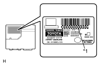
Text in Illustration *1 DCM ID
-
The G-BOOK device uses the DCM (telematics transceiver) to provide access to the network service.
-
The DCM has a DCM ID (described on the label attached to the DCM).
-
As is the case with cellular phones, the DCM has a phone number.
-
-
G-BOOK SUPPORT CENTER OUTLINE
-
The G-BOOK support center provides members with opportunities to ask questions and information necessary for troubleshooting.
G-BOOK Support Center Main Service Outline Answering questions about the G-BOOK system Answering questions from customers about the G-BOOK system Contracting or canceling the G-BOOK online service Performing procedure to make or cancel a contract for customers Confirming server or communication conditions Confirming the G-BOOK center condition Re-registering a G-BOOK device or telematics transceiver Performing procedure for re-registration when the G-BOOK device or telematics transceiver is replaced Answering questions about a manual maintenance check for the emergency call service Answering questions when a manual maintenance check for the emergency call service has not completed normally
-
-
COMMUNICATION SYSTEM
-
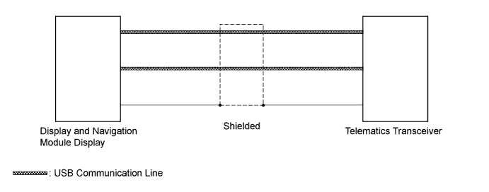
USB Outline
-
G-BOOK system components communicate with each other via the USB.
Tech Tips
If a short or open circuit occurs in the USB circuit, communication will be interrupted and the system will not operate normally.
-
-
-
DIAGNOSTIC FUNCTION OUTLINE
-
The G-BOOK system has a diagnostic function (the result will be displayed on the master unit or intelligent tester).
-
-
DIAGNOSIS DISPLAY DETAILED DESCRIPTION
Tech Tips
This section contains a detailed description of displays in diagnostic mode.
-
Enter diagnostic mode Click here.
-
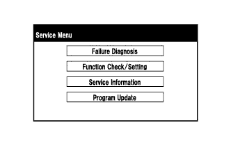
Select "Service Information" on the Service Menu screen.
-
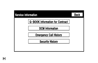
Service Information Screen
Screen Description Display Content G-BOOK Information for Contract The G-BOOK ID, flag information, etc. are displayed. DCM Information The ID, contract information, maintenance check date, etc. which are related to the emergency call service are displayed. Emergency Call History The history (date and condition) of emergency calls is displayed Click here.
Security History The history (date and result) of an alarm notification is displayed Click here.
-
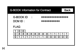
G-BOOK Information for Contract Screen
Screen Description Display Content G-BOOK ID The G-BOOK ID of the display and navigation module display is displayed. DCM ID The 11-digit serial number of the telematics transceiver is displayed. FLAG The G-BOOK contract flag or service flag of the display and navigation module display is displayed. -
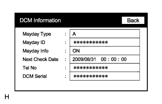
DCM Information Screen
Screen Description Display Content Mayday Type The type of installed emergency call service device is displayed (on this model, "A" (airbag-linked type) is displayed). Mayday ID The ID of the installed emergency call service device is displayed. Mayday Info
-
"ON": Contract has been made and membership has been registered
-
"OFF": Contract has been made but membership has not been registered
-
"NO CONT": Not contracted
The emergency call service contract condition is displayed as follows:
Next Check Date The date on which the automatic maintenance check will be performed next is displayed. Tel No
-
The phone number of the telematics transceiver is displayed.
-
"NO DCM" is displayed when the telematics transceiver is not connected to the display and navigation module display.
DCM Serial
-
The 11-digit serial number of the telematics transceiver is displayed (DCM ID).
-
"NO DCM" is displayed when the telematics transceiver is not connected to the display and navigation module display.
-
-
-
-
WARNING NOTIFICATION FUNCTION
Note
-
Before performing inspections or repairs which may cause warning messages or DTC to occur, such as a simulation test or road test, it is necessary to activate warning notification restraint mode so that the G-BOOK center does not recognize the warnings as real ones.
-
Warning notification restraint mode can be entered by using the intelligent tester or operating the multi-display.
Tech Tips
The warning notification function sends a warning message signal, received from the combination meter assembly via CAN communication, to the G-BOOK center using the G-BOOK device if a warning is displayed due to a vehicle malfunction.
-
Warning notification restraint mode
Tech Tips
-
Performing the following procedure will select warning notification restraint mode.
-
After warning notification restraint mode is entered, driving the vehicle 10 km (6 mile) will cancel the mode.
-
Warning notification restraint mode (Using the intelligent tester)
-
Turn the power switch off.
-
Connect the intelligent tester to the DLC3.
-
Start the engine.
-
Enter the following menus: Powertrain / Engine / DTC.
-
-
Warning notification restraint mode (Operating the multi-display)
-
Enter diagnostic mode of the navigation system (for HDD) Click here.
-
-
-
-
MAYDAY BATTERY OUTLINE
-
As the mayday battery is a non-rechargeable (primary) battery, it cannot be recharged.
-
When it is time to replace the mayday battery, the emergency call switch red indicator will come on. The DCM will also store a DTC.
Note
After automatic emergency call is performed, the mayday battery must be replaced with a new one.
-