NAVIGATION SYSTEM (for HDD) DVD Image Signal Circuit between Radio Receiver and Navigation ECU
DESCRIPTION
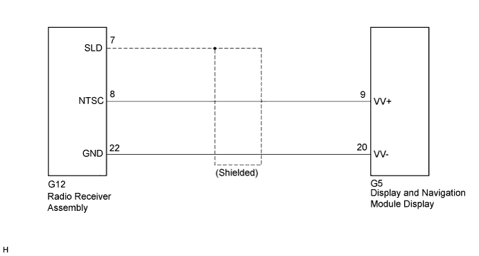
This circuit sends a DVD image signal from the radio receiver assembly to the display and navigation module display.
WIRING DIAGRAM
INSPECTION PROCEDURE
PROCEDURE
-
CHECK HARNESS AND CONNECTOR
-
Disconnect the G12 radio receiver assembly connector.
-
Disconnect the G5 display and navigation module display connector.
-
Measure the resistance according to the value(s) in the table below.
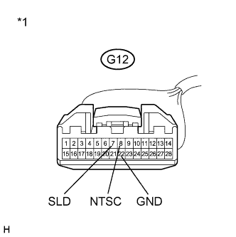
Standard Resistance Tester Connection Condition Specified Condition G12-8 (NTSC) - G5-9 (VV+) Always Below 1 Ω G12-22 (GND) - G5-20 (VV-) Always Below 1 Ω G12-8 (NTSC) - Body ground Always 10 kΩ or higher G12-22 (GND) - Body ground Always 10 kΩ or higher G12-7 (SLD) - Body ground Always 10 kΩ or higher Text in Illustration *1 Front view of wire harness connector
(to Radio Receiver Assembly)
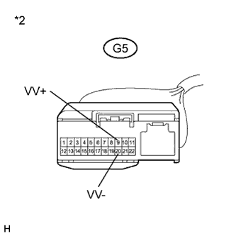
*2 Front view of wire harness connector
(to Display and Navigation Module Display)
NG 
REPAIR OR REPLACE HARNESS OR CONNECTOR
OK 
-
-
INSPECT RADIO RECEIVER ASSEMBLY (DVD IMAGE SIGNAL)
-
Reconnect the G12 radio receiver assembly connector.
-
Check the waveform according to the table below.
-
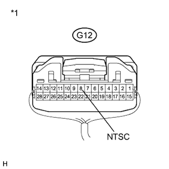
Text in Illustration *1 Component with harness connected
(Radio Receiver Assembly)
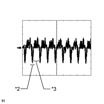
*2 Synchronization Signal *3 Video Waveform Oscilloscope waveform
Item Content Measurement terminal G12-8 (NTSC) - Body ground Measurement setting 200 mV/DIV., 10 μs/DIV. Condition DVD is displayed on multi-display Tech Tips
The video waveform changes according to the image output from the radio receiver assembly to the display and navigation module display, but the synchronization signal does not change.
NG
REPLACE RADIO RECEIVER ASSEMBLY Click here
OK 
PROCEED TO NEXT SUSPECTED AREA SHOWN IN PROBLEM SYMPTOMS TABLE Click here
-