NAVIGATION SYSTEM (for HDD) Display Signal Circuit between Navigation ECU and Multi-display
DESCRIPTION
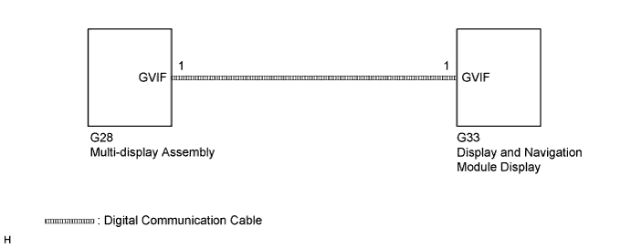
The display image signal*1 from the display and navigation module display is sent to the multi-display assembly using a digital communication cable.
-
*1: Except DVD image signal for vehicles with DVD player.
WIRING DIAGRAM
INSPECTION PROCEDURE
PROCEDURE
-
CHECK DIGITAL COMMUNICATION CABLE CONNECTOR
-
Check digital communication cable connector.
-
Check if the digital communication cable connectors between the display and navigation module display and the multi-display assembly have any connection problems Click here.
-
-
Check that the screen display is normal.
OK Screen display is normal.
NG 
REPLACE WIRE HARNESS (DIGITAL COMMUNICATION CABLE) Click here
OK 
END
-
-
REPLACE WIRE HARNESS (DIGITAL COMMUNICATION CABLE)
-
Replace the digital communication cable between the display and navigation module display and the multi-display assembly.
-
Check that the screen display is normal.
OK Screen display is normal.
NG
REPLACE MULTI-DISPLAY ASSEMBLY Click here
OK
END
-
-
REPLACE MULTI-DISPLAY ASSEMBLY
-
Replace the multi-display assembly Click here.
-
Check that the screen display is normal.
OK Screen display is normal.
NG 
PROCEED TO NEXT SUSPECTED AREA SHOWN IN PROBLEM SYMPTOMS TABLE Click here
OK
END
-