NAVIGATION SYSTEM (for HDD) Parking Brake Switch Circuit
DESCRIPTION
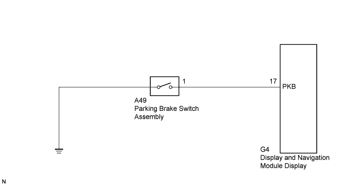
This circuit is from the parking brake switch assembly to the display and navigation module display.
WIRING DIAGRAM
INSPECTION PROCEDURE
PROCEDURE
-
CHECK BRAKE WARNING LIGHT
-
Check that the brake warning light comes on when the parking brake is applied and goes off when it is released.
OK The brake warning light operates as specified above.
NG 
INSPECT PARKING BRAKE SWITCH ASSEMBLY Click here
OK 
-
-
CHECK HARNESS AND CONNECTOR
-
Disconnect the G4 display and navigation module display connector.
-
Disconnect the A49 parking brake switch assembly connector.
-
Measure the resistance according to the value(s) in the table below.
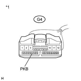
Standard Resistance Tester connection Condition Specified condition G4-17 (PKB) - A49-1 Always Below 1 Ω G4-17 (PKB) - Body ground Always 10 kΩ or higher Text in Illustration *1 Front view of wire harness connector
(to Display and Navigation Module Display)
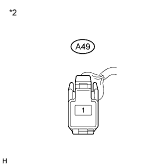
*2 Front view of wire harness connector
(to Parking Brake Switch Assembly)
NG 
REPAIR OR REPLACE HARNESS OR CONNECTOR
OK 
PROCEED TO NEXT SUSPECTED AREA SHOWN IN PROBLEM SYMPTOMS TABLE Click here
-
-
INSPECT PARKING BRAKE SWITCH ASSEMBLY
-
Disconnect the parking brake switch assembly connector.
-
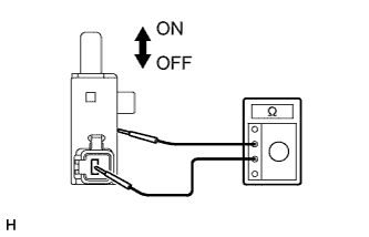
Measure the resistance according to the value(s) in the table below.
Standard Resistance Tester connection Condition Specified condition Switch connector - Switch body ON (When shaft is not pressed) Below 1 Ω Switch connector - Switch body OFF (When shaft is pressed) 10 kΩ or higher -
Proceed to the next step based on the inspection result.
Result Result Proceed to OK A NG (for LHD) B NG (for RHD) C
B
REPLACE PARKING BRAKE SWITCH ASSEMBLY (for LHD) Click here
C
REPLACE PARKING BRAKE SWITCH ASSEMBLY (for RHD) Click here
A
REPAIR OR REPLACE HARNESS OR CONNECTOR
-