NAVIGATION SYSTEM (for HDD) Microphone Circuit between Microphone and Navigation ECU
DESCRIPTION
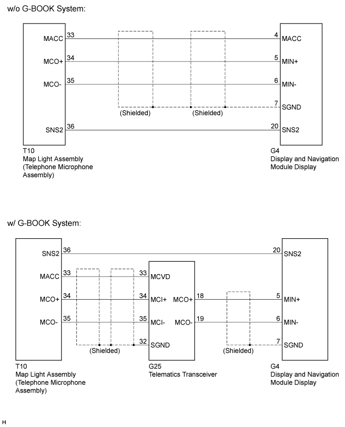
The display and navigation module display and map light assembly (telephone microphone assembly) are connected to each other using the microphone connection detection signal lines.
Using this circuit, the display and navigation module display sends power to the map light assembly (telephone microphone assembly), and the map light assembly sends microphone signals to the display and navigation module display. (w/o G-BOOK system)
Using this circuit, the telematics transceiver sends power to the map light assembly (telephone microphone assembly), and the map light assembly (telephone microphone assembly) sends microphone signals to the display and navigation module display via the telematics transceiver. (w/ G-BOOK system)
WIRING DIAGRAM
INSPECTION PROCEDURE
Note
When replacing the display and navigation module display or telematics transceiver, perform vehicle contract setting (w/ G-BOOK system) Click here.
PROCEDURE
-
CONFIRM MODEL
-
Choose the model to be inspected.
Result Model Proceed to w/o G-BOOK System A w/ G-BOOK System B
B 
CHECK HARNESS AND CONNECTOR Click here
A 
-
-
CHECK HARNESS AND CONNECTOR
-
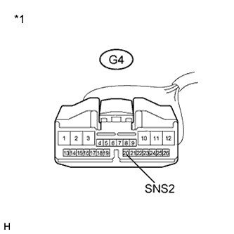
Disconnect the G4 display and navigation module display connector.
-
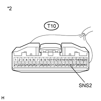
Disconnect the T10 map light assembly connector.
-
Measure the resistance according to the value(s) in the table below.
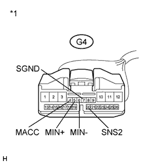
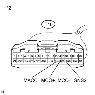
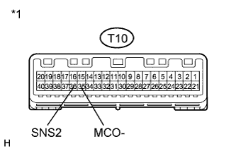
Standard Resistance Tester Connection Condition Specified Condition G4-20 (SNS2) - T10-36 (SNS2) Always Below 1 Ω G4-4 (MACC) - T10-33 (MACC) Always Below 1 Ω G4-5 (MIN+) - T10-34 (MCO+) Always Below 1 Ω G4-6 (MIN-) - T10-35 (MCO-) Always Below 1 Ω G4-20 (SNS2) - Body ground Always 10 kΩ or higher G4-4 (MACC) - Body ground Always 10 kΩ or higher G4-5 (MIN+) - Body ground Always 10 kΩ or higher G4-6 (MIN-) - Body ground Always 10 kΩ or higher G4-7 (SGND) - Body ground Always 10 kΩ or higher Text in Illustration *1 Front view of wire harness connector
(to Display and Navigation Module Display)
*2 Front view of wire harness connector
(to Map Light Assembly)
NG 
REPAIR OR REPLACE HARNESS OR CONNECTOR
OK
-
-
INSPECT DISPLAY AND NAVIGATION MODULE DISPLAY
-
Disconnect the T10 map light assembly connector.
-
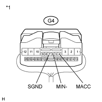
Text in Illustration *1 Component with harness connected
(Display and Navigation Module Display)
Reconnect the G4 display and navigation module display connector.
-
Measure the voltage according to the value(s) in the table below.
Standard Voltage Tester Connection Condition Specified Condition G4-4 (MACC) - Body ground Power switch on (ACC) 4 to 6 V -
Measure the resistance according to the value(s) in the table below.
Standard Resistance Tester Connection Condition Specified Condition G4-7 (SGND) - Body ground Always Below 1 Ω G4-6 (MIN-) - Body ground Always Below 1 Ω -
Proceed to the next step based on the inspection result.
Result Result Proceed to NG A OK B
B
INSPECT MAP LIGHT ASSEMBLY Click here
A 
REPLACE DISPLAY AND NAVIGATION MODULE DISPLAY Click here
-
-
CHECK HARNESS AND CONNECTOR
-
Disconnect the G4 display and navigation module display connector.
-
Disconnect the T10 map light assembly connector.
-
Measure the resistance according to the value(s) in the table below.
Standard Resistance Tester Connection Condition Specified Condition G4-20 (SNS2) - T10-36 (SNS2) Always Below 1 Ω Text in Illustration *1 Front view of wire harness connector
(to Display and Navigation Module Display)
*2 Front view of wire harness connector
(to Map Light Assembly)
NG
REPAIR OR REPLACE HARNESS OR CONNECTOR
OK
-
-
CHECK HARNESS AND CONNECTOR
-
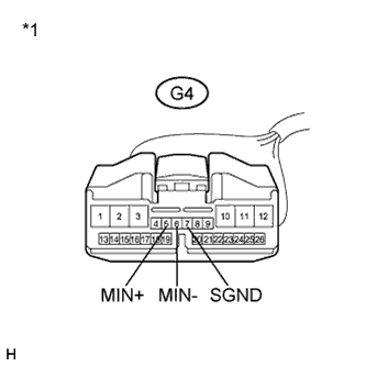
Disconnect the G4 display and navigation module display connector.
-
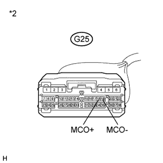
Disconnect the G25 telematics transceiver connector.
-
Measure the resistance according to the value(s) in the table below.
Standard Resistance Tester Connection Condition Specified Condition G4-5 (MIN+) - G25-18 (MCO+) Always Below 1 Ω G4-6 (MIN-) - G25-19 (MCO-) Always Below 1 Ω G4-5 (MIN+) - Body ground Always 10 kΩ or higher G4-6 (MIN-) - Body ground Always 10 kΩ or higher G4-7 (SGND) - Body ground Always 10 kΩ or higher Text in Illustration *1 Front view of wire harness connector
(to Display and Navigation Module Display)
*2 Front view of wire harness connector
(to Telematics Transceiver)
NG
REPAIR OR REPLACE HARNESS OR CONNECTOR
OK
-
-
CHECK HARNESS AND CONNECTOR
-
Disconnect the G25 telematics transceiver connector.
-
Disconnect the T10 map light assembly connector.
-
Measure the resistance according to the value(s) in the table below.
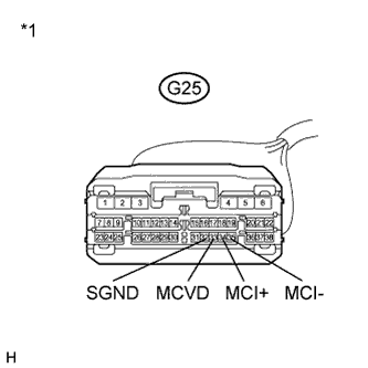
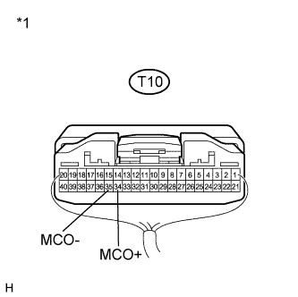
Standard Resistance Tester Connection Condition Specified Condition G25-33 (MCVD) - T10-33 (MACC) Always Below 1 Ω G25-34 (MCI+) - T10-34 (MCO+) Always Below 1 Ω G25-35 (MCI-) - T10-35 (MCO-) Always Below 1 Ω G25-33 (MCVD) - Body ground Always 10 kΩ or higher G25-34 (MCI+) - Body ground Always 10 kΩ or higher G25-35 (MCI-) - Body ground Always 10 kΩ or higher G25-32 (SGND) - Body ground Always 10 kΩ or higher Text in Illustration *1 Front view of wire harness connector
(to Telematics Transceiver)
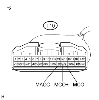
*2 Front view of wire harness connector
(to Map Light Assembly)
NG
REPAIR OR REPLACE HARNESS OR CONNECTOR
OK
-
-
INSPECT DISPLAY AND NAVIGATION MODULE DISPLAY
-
Disconnect the G25 telematics transceiver connector.
-
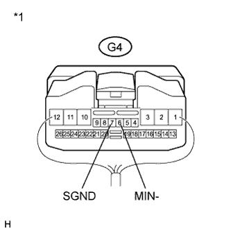
Text in Illustration *1 Component with harness connected
(Display and Navigation Module Display)
Reconnect the G4 display and navigation module display connector.
-
Measure the resistance according to the value(s) in the table below.
Standard Resistance Tester Connection Condition Specified Condition G4-7 (SGND) - Body ground Always Below 1 Ω G4-6 (MIN-) - Body ground Always Below 1 Ω
NG
REPLACE DISPLAY AND NAVIGATION MODULE DISPLAY Click here
OK
-
-
INSPECT TELEMATICS TRANSCEIVER
-
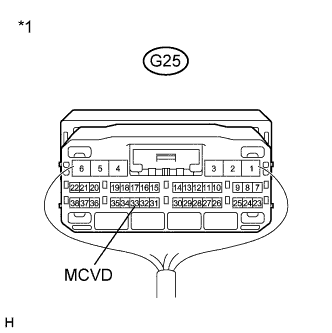
Text in Illustration *1 Component with harness connected
(Telematics Transceiver)
Measure the voltage according to the value(s) in the table below.
Standard Voltage Tester Connection Condition Specified Condition G25-33 (MCVD) - Body ground Power switch on (ACC) 4 to 6 V
NG
REPLACE TELEMATICS TRANSCEIVER Click here
OK
-
-
INSPECT MAP LIGHT ASSEMBLY
-
Text in Illustration *1 Component without harness connected
(Map Light Assembly)
Measure the resistance according to the value(s) in the table below.
Standard Resistance Tester Connection Condition Specified Condition T10-36 (SNS2) - T10-35 (MCO-) Always Below 1 Ω
NG
REPLACE TELEPHONE MICROPHONE ASSEMBLY Click here
OK
-
-
INSPECT MAP LIGHT ASSEMBLY
-
Reconnect the G4 display and navigation module display connector.
-
Reconnect the G25 telematics transceiver connector. (w/ G-BOOK system)
-
Text in Illustration *1 Component with harness connected
(Map Light Assembly)
Reconnect the T10 map light assembly connector.
-
Turn the power switch on (ACC).
-
Connect an oscilloscope to terminals 34 (MCO+) and 35 (MCO-) of the T10 map light assembly connector.
-
Check the waveform of the telephone microphone assembly using an oscilloscope.
Result Result Proceed to A waveform synchronized with the voice input to the map light assembly is output A A waveform synchronized with the voice input to the map light assembly is not output B
B
REPLACE TELEPHONE MICROPHONE ASSEMBLY Click here
A
PROCEED TO NEXT SUSPECTED AREA SHOWN IN PROBLEM SYMPTOMS TABLE Click here
-
-
REPLACE TELEPHONE MICROPHONE ASSEMBLY
-
Replace the telephone microphone assembly Click here.
-
Check if the same malfunction recurs.
Result Result Proceed to Malfunction does not recur
(returns to normal)
A Malfunction recurs B
B
REPLACE MAP LIGHT ASSEMBLY Click here
A
END
-