NAVIGATION SYSTEM (for HDD) Visual Mute Signal Circuit between Navigation ECU and Multi-display
DESCRIPTION
The display and navigation module display sends a visual mute signal to the multi-display assembly. As a result, a black screen is inserted when the screen changes so that noise and distorted images are not displayed.
When an open exists in the circuit, noise and distorted images will be displayed instead of a black screen.
When a short exists in the circuit, even though the multi-display assembly is operating normally, noise and distorted images will be displayed (black screen will not be displayed) during screen changes or the black screen will always be displayed.
WIRING DIAGRAM
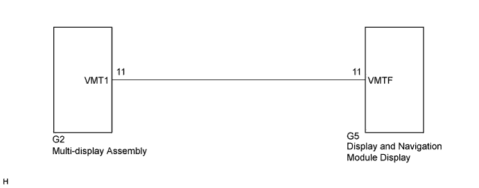
INSPECTION PROCEDURE
Note
When replacing the display and navigation module display, perform vehicle contract setting (w/ G-BOOK system) Click here.
PROCEDURE
-
INSPECT MULTI-DISPLAY ASSEMBLY
-
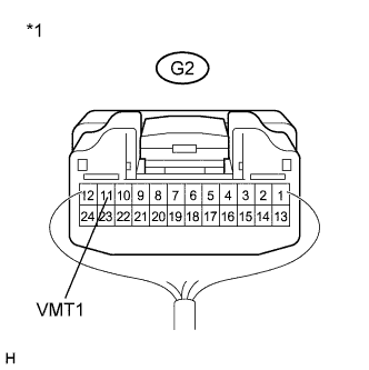
Text in Illustration *1 Component with harness connected
(Multi-display Assembly)
Measure the voltage according to the value(s) in the table below.
Standard Voltage Tester Connection Condition Specified Condition G2-11 (VMT1) - Body ground Power switch on (ACC), screen display changes. 3.5 V or higher → Below 1 V → 3.5 V or higher
NG 
CHECK HARNESS AND CONNECTOR Click here
OK 
PROCEED TO NEXT SUSPECTED AREA SHOWN IN PROBLEM SYMPTOMS TABLE Click here
-
-
CHECK HARNESS AND CONNECTOR
-
Disconnect the G2 multi-display assembly connector.
-
Disconnect the G5 display and navigation module display connector.
-
Measure the resistance according to the value(s) in the table below.
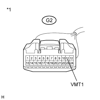
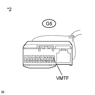
Standard Resistance Tester Connection Condition Specified Condition G2-11 (VMT1) - G5-11 (VMTF) Always Below 1 Ω G2-11 (VMT1) - Body ground Always 10 kΩ or higher Text in Illustration *1 Front view of wire harness connector
(to Multi-display Assembly)
*2 Front view of wire harness connector
(to Display and Navigation Module Display)
NG 
REPAIR OR REPLACE HARNESS OR CONNECTOR
OK 
-
-
REPLACE MULTI-DISPLAY ASSEMBLY
-
Replace the multi-display assembly and check if it operates normally Click here.
OK The navigation system operates normally.
NG
REPLACE DISPLAY AND NAVIGATION MODULE DISPLAY Click here
OK
END
-