NAVIGATION SYSTEM (for HDD) Display does not Dim when Light Control Switch is Turned ON
DESCRIPTION
When the navigation system is activated with the light control switch in the tail or head position, before AVC-LAN communication is established, the multi-display assembly dims the display according to the illumination signal received via a direct line.
After AVC-LAN communication is established, the multi-display assembly dims the display according to a dimmer signal sent via AVC-LAN communication.
The display and navigation module display switches between the daytime screen and night screen on the multi-display according to the illumination signal input.
WIRING DIAGRAM
-
for LHD
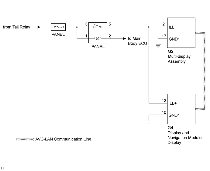
-
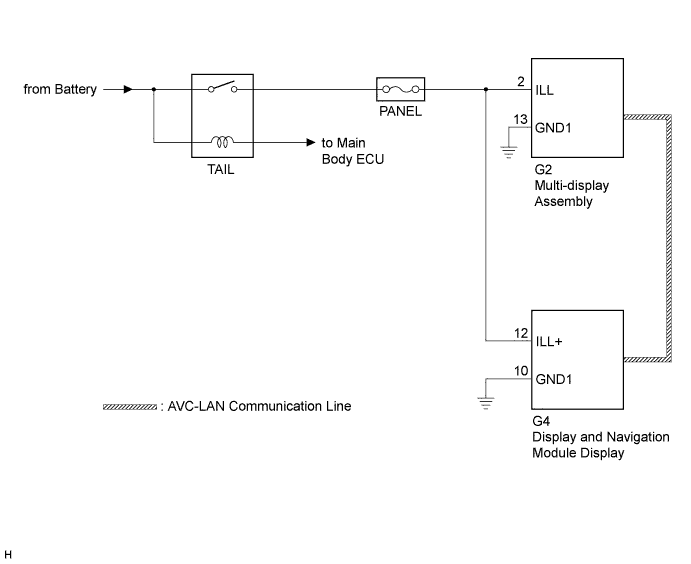
for RHD
INSPECTION PROCEDURE
Note
Inspect the fuses for circuits related to this system before performing the following inspection procedure.
PROCEDURE
-
CONFIRM SYMPTOMS
-
Check the symptoms that occur by viewing the display.
Result Result Proceed to There is a delay until the display dims after the navigation system is activated with the light control switch in the tail or head position. A The display dims for a moment and then becomes bright after the navigation system is activated with the light control switch in the tail or head position. B When the light control switch is set to the tail or head position, the display dims but does not switch to the night screen. B When the light control switch is set to the tail or head position, the display neither dims nor switches to the night screen. C Tech Tips
-
When the navigation system is activated with the light control switch in the tail or head position, before AVC-LAN communication is established, the multi-display assembly dims the display according to the illumination signal received via a direct line.
-
After AVC-LAN communication is established, the multi-display assembly dims the display according to a dimmer signal sent via AVC-LAN communication.
-
The display and navigation module display switches between the daytime screen and night screen on the multi-display according to the illumination signal input.
-
B 
CHECK IMAGE QUALITY SETTING Click here
C 
GO TO LIGHTING SYSTEM Click here
A 
-
-
CHECK HARNESS AND CONNECTOR (ILLUMINATION SIGNAL)
-
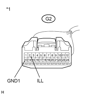
Text in Illustration *1 Front view of wire harness connector
(to Multi-display Assembly)
Disconnect the G2 multi-display assembly connector.
-
Measure the resistance according to the value(s) in the table below.
Standard Resistance Tester Connection Condition Specified Condition G2-13 (GND1) - Body ground Always Below 1 Ω -
Measure the voltage according to the value(s) in the table below.
Standard Voltage Tester Connection Condition Specified Condition G2-2 (ILL) - G2-13 (GND1) Light control switch in tail or head 11 to 14 V
NG
REPAIR OR REPLACE HARNESS OR CONNECTOR
OK 
PROCEED TO NEXT SUSPECTED AREA SHOWN IN PROBLEM SYMPTOMS TABLE Click here
-
-
CHECK IMAGE QUALITY SETTING
-
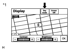
Text in Illustration *1 Example Press the "DISP" switch on the remote touch.
-
Turn the light control switch to the tail position.
-
Check if "Day mode" on the display adjustment screen is on.
Result Result Proceed to "Day mode" is on A "Day mode" is off B
B
CHECK VEHICLE SIGNAL (OPERATION CHECK) Click here
A
TURN "Day Mode" SETTING OFF
-
-
CHECK VEHICLE SIGNAL (OPERATION CHECK)
-
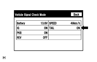
Enter the "Vehicle Signal Check Mode" screen. Refer to Check Vehicle Signal in Operation Check Click here.
-
Check that the display changes between ON and OFF according to the light control switch operation.
OK Light Control Switch Display Tail or head ON Off OFF Tech Tips
The display is updated once per second. It is normal for the display to lag behind the actual switch operation.
NG
CHECK HARNESS AND CONNECTOR (ILLUMINATION SIGNAL) Click here
OK
PROCEED TO NEXT SUSPECTED AREA SHOWN IN PROBLEM SYMPTOMS TABLE Click here
-
-
CHECK HARNESS AND CONNECTOR (ILLUMINATION SIGNAL)
-
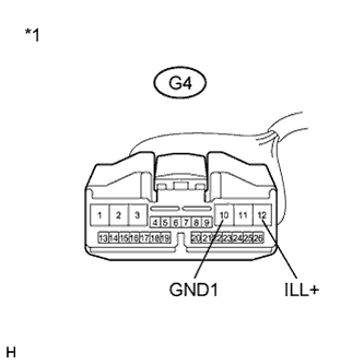
Text in Illustration *1 Front view of wire harness connector
(to Display and Navigation Module Display)
Disconnect the G4 display and navigation module display connector.
-
Measure the resistance according to the value(s) in the table below.
Standard Resistance Tester Connection Condition Specified Condition G4-10 (GND1) - Body ground Always Below 1 Ω -
Measure the voltage according to the value(s) in the table below.
Standard Voltage Tester Connection Condition Specified Condition G4-12 (ILL+) - G4-10 (GND1) Light control switch at tail or head 11 to 14 V
NG
REPAIR OR REPLACE HARNESS OR CONNECTOR
OK
PROCEED TO NEXT SUSPECTED AREA SHOWN IN PROBLEM SYMPTOMS TABLE Click here
-