NAVIGATION SYSTEM (for HDD), Diagnostic DTC:B1595, B15D5

| DTC Code | DTC Name |
|---|---|
| B1595 | No Response from Rear Seat Entertainment System |
| B15D5 | Rear Seat Entertainment System Disconnected |
DESCRIPTION
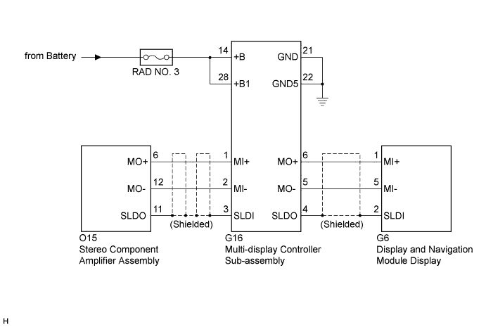
The display and navigation module display and the multi-display controller sub-assembly are connected by the MOST communication line.
When a MOST communication error occurs between the display and navigation module display and the multi-display controller sub-assembly, these DTCs will be stored.
| DTC No. | DTC Detection Condition | Trouble Area |
|---|---|---|
| B1595 | No response to the diagnostic memory request from the master unit. |
|
| B15D5 | A device that is listed in the MOST network connected device record of the master unit is missing. |
Tech Tips
For the MOST network, the display and navigation module display is the master unit.
WIRING DIAGRAM
INSPECTION PROCEDURE
Note
-
Inspect the fuses for circuits related to this system before performing the following inspection procedure.
-
When replacing the display and navigation module display, perform vehicle contract setting (w/ G-BOOK system) Click here.
PROCEDURE
-
CHECK OPTIONAL COMPONENTS (INCLUDING ASSOCIATED WIRING)
-
Check for optional components.
-
Check that optional components (including associated wiring) which generate radio waves are not installed.
Result Result Proceed to Optional components (including associated wiring) are installed. A Optional components (including associated wiring) are not installed. B Tech Tips
-
Electrical noise from radio waves generated by optional components or the wiring for those components may affect MOST communication.
-
This DTC may be stored when a MOST communication error occurs due to electrical noise.
-
-
B 
CHECK DTC Click here
A 
-
-
REMOVE OPTIONAL COMPONENTS (INCLUDING ASSOCIATED WIRING)
-
Remove optional components (including associated wiring).
Note
Do not remove optional components or associated wiring without the permission of the customer.
NEXT
-
-
CHECK DTC
-
Clear the DTCs Click here.
-
Recheck for DTCs and check if the same DTC is output again.
OK No DTCs are output.
NG
CHECK HARNESS AND CONNECTOR (MULTI-DISPLAY CONTROLLER SUB-ASSEMBLY POWER SOURCE) Click here
OK 
END
-
-
CHECK HARNESS AND CONNECTOR (MULTI-DISPLAY CONTROLLER SUB-ASSEMBLY POWER SOURCE)
-
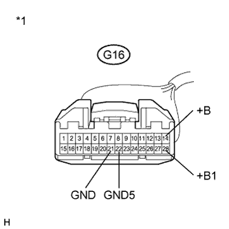
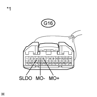
Text in Illustration *1 Front view of wire harness connector
(to Multi-display Controller Sub-assembly)
Disconnect the G16 multi-display controller sub-assembly connector.
-
Measure the resistance according to the value(s) in the table below.
Standard Resistance Tester Connection Condition Specified Condition G16-21 (GND) - Body ground Always Below 1 Ω G16-22 (GND5) - Body ground Always Below 1 Ω -
Measure the voltage according to the value(s) in the table below.
Standard Voltage Tester Connection Condition Specified Condition G16-14 (+B) - G16-21 (GND) Power switch off 11 to 14 V G16-28 (+B1) - G16-21 (GND) Power switch off 11 to 14 V
NG 
REPAIR OR REPLACE HARNESS OR CONNECTOR
OK
-
-
CHECK HARNESS AND CONNECTOR
-
Disconnect the G16 multi-display controller sub-assembly connector.
-
Disconnect the O15 stereo component amplifier assembly connector.
-
Measure the resistance according to the value(s) in the table below.
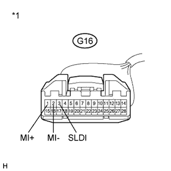
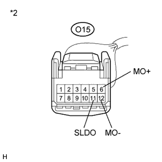
Standard Resistance Tester Connection Condition Specified Condition G16-1 (MI+) - O15-6 (MO+) Always Below 1 Ω G16-2 (MI-) - O15-12 (MO-) Always Below 1 Ω G16-3 (SLDI) - O15-11 (SLDO) Always Below 1 Ω G16-1 (MI+) - Body ground Always 10 kΩ or higher G16-2 (MI-) - Body ground Always 10 kΩ or higher G16-3 (SLDI) - Body ground Always 10 kΩ or higher Text in Illustration *1 Front view of wire harness connector
(to Multi-display Controller Sub-assembly)
*2 Front view of wire harness connector
(to Stereo Component Amplifier Assembly)
NG
REPAIR OR REPLACE HARNESS OR CONNECTOR
OK
-
-
CHECK HARNESS AND CONNECTOR
-
Disconnect the G16 multi-display controller sub-assembly connector.
-
Disconnect the G6 display and navigation module display connector.
-
Measure the resistance according to the value(s) in the table below.
Standard Resistance Tester Connection Condition Specified Condition G16-6 (MO+) - G6-1 (MI+) Always Below 1 Ω G16-5 (MO-) - G6-5 (MI-) Always Below 1 Ω G16-4 (SLDO) - G6-2 (SLDI) Always Below 1 Ω G16-6 (MO+) - Body ground Always 10 kΩ or higher G16-5 (MO-) - Body ground Always 10 kΩ or higher G16-4 (SLDO) - Body ground Always 10 kΩ or higher Text in Illustration *1 Front view of wire harness connector
(to Multi-display Controller Sub-assembly)
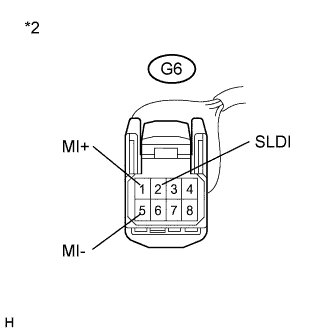
*2 Front view of wire harness connector
(to Display and Navigation Module Display)
NG
REPAIR OR REPLACE HARNESS OR CONNECTOR
OK
-
-
REPLACE MULTI-DISPLAY CONTROLLER SUB-ASSEMBLY
-
Replace the multi-display controller sub-assembly Click here.
-
Clear the DTCs Click here.
-
Recheck for DTCs and check if the same DTC is output again.
OK No DTCs are output.
NG
REPLACE DISPLAY AND NAVIGATION MODULE DISPLAY Click here
OK
END
-