NAVIGATION SYSTEM (for HDD), Diagnostic DTC:B1593, B15D3

| DTC Code | DTC Name |
|---|---|
| B1593 | No Response from Stereo Component Amplifier |
| B15D3 | Stereo Component Amplifier Disconnected |
DESCRIPTION
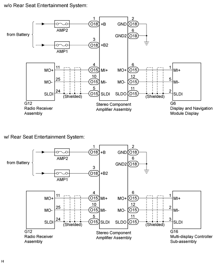
The display and navigation module display and the stereo component amplifier assembly are connected by the MOST communication line.
When a MOST communication error occurs between the display and navigation module display and the stereo component amplifier assembly, these DTCs will be stored.
| DTC No. | DTC Detection Condition | Trouble Area |
|---|---|---|
| B1593 | No response to the diagnostic memory request from the master unit. |
|
| B15D3 | A device that is listed in the MOST network connected device record of the master unit is missing. |
Tech Tips
For the MOST network, the display and navigation module display is the master unit.
WIRING DIAGRAM
INSPECTION PROCEDURE
Note
-
Inspect the fuses for circuits related to this system before performing the following inspection procedure.
-
When replacing the display and navigation module display, perform vehicle contract setting (w/ G-BOOK system) Click here.
PROCEDURE
-
CHECK OPTIONAL COMPONENTS (INCLUDING ASSOCIATED WIRING)
-
Check for optional components.
-
Check that optional components (including associated wiring) which generate radio waves are not installed.
Result Result Proceed to Optional components (including associated wiring) are installed. A Optional components (including associated wiring) are not installed. B Tech Tips
-
Electrical noise from radio waves generated by optional components or the wiring for those components may affect MOST communication.
-
This DTC may be stored when a MOST communication error occurs due to electrical noise.
-
-
B 
CHECK DTC Click here
A 
-
-
REMOVE OPTIONAL COMPONENTS (INCLUDING ASSOCIATED WIRING)
-
Remove optional components (including associated wiring).
Note
Do not remove optional components or associated wiring without the permission of the customer.
NEXT
-
-
CHECK DTC
-
Clear the DTCs Click here.
-
Recheck for DTCs and check if the same DTC is output again.
OK No DTCs are output.
NG
CHECK HARNESS AND CONNECTOR (STEREO COMPONENT AMPLIFIER POWER SOURCE) Click here
OK 
END
-
-
CHECK HARNESS AND CONNECTOR (STEREO COMPONENT AMPLIFIER POWER SOURCE)
-
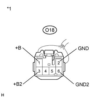
Text in Illustration *1 Front view of wire harness connector
(to Stereo Component Amplifier Assembly)
Disconnect the O18 stereo component amplifier assembly connector.
-
Measure the resistance according to the value(s) in the table below.
Standard Resistance Tester Connection Condition Specified Condition O18-2 (GND) - Body ground Always Below 1 Ω O18-6 (GND2) - Body ground Always Below 1 Ω -
Measure the voltage according to the value(s) in the table below.
Standard Voltage Tester Connection Condition Specified Condition O18-1 (+B) - O18-2 (GND) Power switch off 11 to 14 V O18-3 (+B2) - O18-2 (GND) Power switch off 11 to 14 V
NG 
REPAIR OR REPLACE HARNESS OR CONNECTOR
OK
-
-
CHECK HARNESS AND CONNECTOR
-
Disconnect the O15 stereo component amplifier assembly connector.
-
Disconnect the G12 radio receiver assembly connector.
-
Measure the resistance according to the value(s) in the table below.
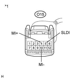
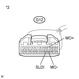
Standard Resistance Tester Connection Condition Specified Condition O15-4 (MI+) - G12-11 (MO+) Always Below 1 Ω O15-10 (MI-) - G12-25 (MO-) Always Below 1 Ω O15-5 (SLDI) - G12-24 (SLDI) Always Below 1 Ω O15-4 (MI+) - Body ground Always 10 kΩ or higher O15-10 (MI-) - Body ground Always 10 kΩ or higher O15-5 (SLDI) - Body ground Always 10 kΩ or higher Text in Illustration *1 Front view of wire harness connector
(to Stereo Component Amplifier Assembly)
*2 Front view of wire harness connector
(to Radio Receiver Assembly)
NG
REPAIR OR REPLACE HARNESS OR CONNECTOR
OK
-
-
CONFIRM MODEL
-
Choose the model to be inspected.
Result Model Proceed to w/o Rear Seat Entertainment System A w/ Rear Seat Entertainment System B
B
CHECK HARNESS AND CONNECTOR Click here
A
-
-
CHECK HARNESS AND CONNECTOR
-
Disconnect the O15 stereo component amplifier assembly connector.
-
Disconnect the G6 display and navigation module display connector.
-
Measure the resistance according to the value(s) in the table below.
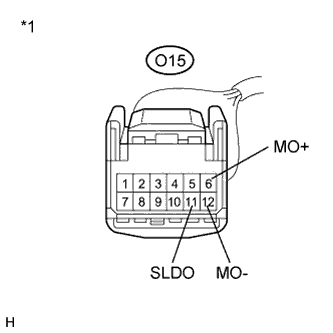
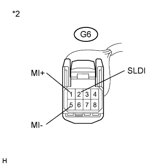
Standard Resistance Tester Connection Condition Specified Condition O15-6 (MO+) - G6-1 (MI+) Always Below 1 Ω O15-12 (MO-) - G6-5 (MI-) Always Below 1 Ω O15-11 (SLDO) - G6-2 (SLDI) Always Below 1 Ω O15-6 (MO+) - Body ground Always 10 kΩ or higher O15-12 (MO-) - Body ground Always 10 kΩ or higher O15-11 (SLDO) - Body ground Always 10 kΩ or higher Text in Illustration *1 Front view of wire harness connector
(to Stereo Component Amplifier Assembly)
*2 Front view of wire harness connector
(to Display and Navigation Module Display)
NG
REPAIR OR REPLACE HARNESS OR CONNECTOR
OK
-
-
REPLACE STEREO COMPONENT AMPLIFIER ASSEMBLY
-
Replace the stereo component amplifier assembly Click here.
-
Clear the DTCs Click here.
-
Recheck for DTCs and check if the same DTC is output again.
OK No DTCs are output.
NG
REPLACE DISPLAY AND NAVIGATION MODULE DISPLAY Click here
OK
END
-
-
CHECK HARNESS AND CONNECTOR
-
Disconnect the O15 stereo component amplifier assembly connector.
-
Disconnect the G16 multi-display controller sub-assembly connector.
-
Measure the resistance according to the value(s) in the table below.
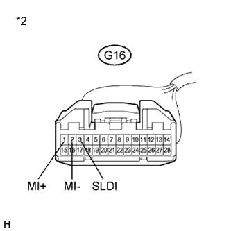
Standard Resistance Tester Connection Condition Specified Condition O15-6 (MO+) - G16-1 (MI+) Always Below 1 Ω O15-12 (MO-) - G16-2 (MI-) Always Below 1 Ω O15-11 (SLDO) - G16-3 (SLDI) Always Below 1 Ω O15-6 (MO+) - Body ground Always 10 kΩ or higher O15-12 (MO-) - Body ground Always 10 kΩ or higher O15-11 (SLDO) - Body ground Always 10 kΩ or higher Text in Illustration *1 Front view of wire harness connector
(to Stereo Component Amplifier Assembly)
*2 Front view of wire harness connector
(to Multi-display Controller Sub-assembly)
NG
REPAIR OR REPLACE HARNESS OR CONNECTOR
OK
-
-
REPLACE STEREO COMPONENT AMPLIFIER ASSEMBLY
-
Replace the stereo component amplifier assembly Click here.
-
Clear the DTCs Click here.
-
Recheck for DTCs and check if the same DTC is output again.
OK No DTCs are output.
NG
REPLACE DISPLAY AND NAVIGATION MODULE DISPLAY Click here
OK
END
-