NAVIGATION SYSTEM (for HDD), Diagnostic DTC:B15D0

| DTC Code | DTC Name |
|---|---|
| B15D0 | MOST Communication Malfunction |
DESCRIPTION
This DTC is stored when the MOST network cannot be established after the master unit is activated.
Tech Tips
-
If a short occurs in a speaker circuit, the sound from the corresponding speaker will be low or almost impossible to hear. If the volume is turned up in this situation, to prevent excessive current flow due to the short circuit, the stereo component amplifier assembly stops operating when its output exceeds a certain level. When the operation of the stereo component amplifier assembly stops, the navigation system will not function normally. This is because MOST communication will stop due to the shut down of the amplifier causing an error in the MOST network. The stereo component amplifier assembly will start operating again when the power switch is turned off and back on (ACC) again. However, the amplifier will stop operating again if its output exceeds a certain level. (for 15 speakers)
-
When the stereo component amplifier assembly stops operating and a malfunction occurs in the navigation system due to a short in a speaker circuit, this DTC will be stored. (for 15 speakers)
| DTC No. | DTC Detection Condition | Trouble Area |
|---|---|---|
| B15D0 | MOST network cannot be established. |
|
Tech Tips
-
For the MOST network, the display and navigation module display is the master unit.
-
Errors may occur in MOST communication between devices due to problems such as electrical noise.
WIRING DIAGRAM
-
w/o Rear Seat Entertainment System
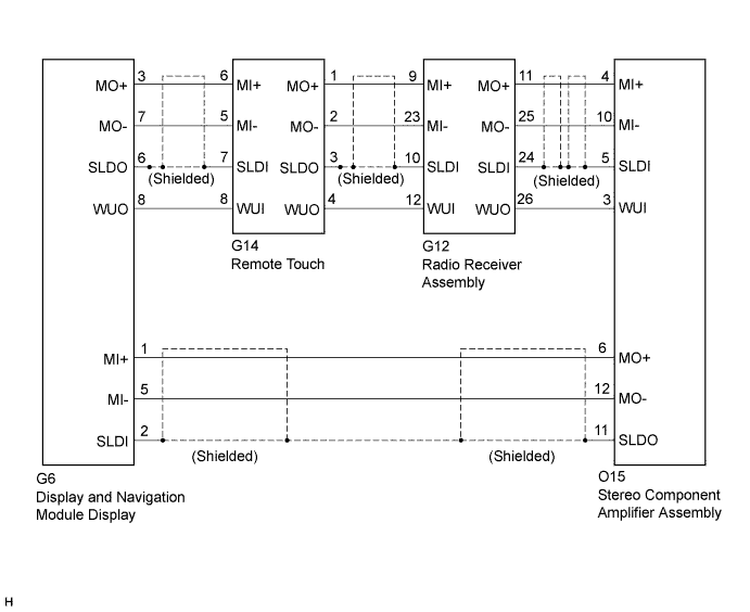
-
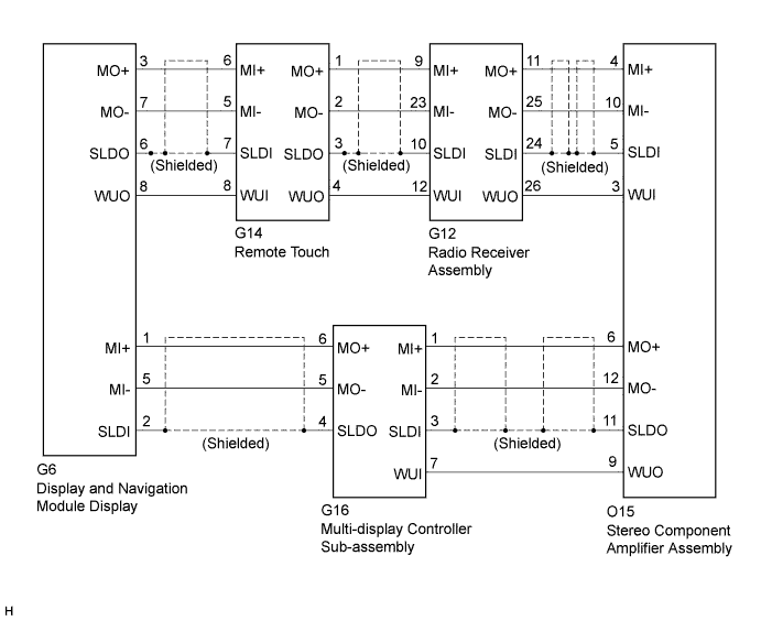
w/ Rear Seat Entertainment System
INSPECTION PROCEDURE
Note
When replacing the display and navigation module display, perform vehicle contract setting (w/ G-BOOK system) Click here.
PROCEDURE
-
CONFIRM MODEL
-
Choose the model to be inspected.
Result Model Proceed to for 15 speakers A except 15 speakers B
B 
PERFORM MOST LINE CHECK Click here
A 
-
-
CONFIRM SYMPTOMS
-
Turn the power switch off.
-
Turn the power switch on (ACC) and check if the audio system activates and if the speakers operate.
Tech Tips
-
Choose a source such as radio so that sound can be output from the speakers.
-
If sound from the speakers is low, turn up the volume.
Result Model Proceed to The audio system activates when the power switch is turned on (ACC) but the sound stops being output when the amplifier output exceeds a certain level. A Even after the power switch is turned on (ACC), the audio system does not activate and sound is not output from the speakers. B Tech Tips
-
If a short occurs in a speaker circuit, the sound from the corresponding speaker will be low or almost impossible to hear. If the volume is turned up in this situation, to prevent excessive current flow due to the short circuit, the stereo component amplifier assembly stops operating when its output exceeds a certain level. When the operation of the stereo component amplifier assembly stops, the navigation system will not function normally. This is because MOST communication will stop due to the shut down of the amplifier causing an error in the MOST network. The stereo component amplifier assembly will start operating again when the power switch is turned off and back on (ACC) again. However, the amplifier will stop operating again if its output exceeds a certain level.
-
When the stereo component amplifier assembly stops operating and a malfunction occurs in the navigation system due to a short in a speaker circuit, this DTC will be stored. In this case, check each speaker circuit and repair or replace malfunctioning parts, and then recheck for DTCs.
-
B
PERFORM MOST LINE CHECK Click here
A 
GO TO AUDIO AND VISUAL SYSTEM (w/ Navigation System) Click here
-
-
PERFORM MOST LINE CHECK
-
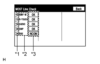
Text in Illustration *1 Node position number for devices that use MOST communication *2 Device name *3 Result Display the "MOST Line Check" screen Click here.
-
Check the result on the "MOST Line Check" screen.
Result Result Proceed to "NCON" is displayed for "R-TOUC". A "NCON" is displayed for "AUDIO". B "NCON" is displayed for "AMP". C "NCON" is displayed for "RSE". (w/ rear seat entertainment system) D "OK" is displayed for all items. E Tech Tips
-
When "NCON" is displayed for more than 1 item, proceed to the step for the device that has the smallest node position number.
-
The "MOST Line Check" screen can be displayed only when DTC B15D0 is stored.
-
B
CHECK MOST COMMUNICATION CONNECTORS Click here
C
CHECK MOST COMMUNICATION CONNECTORS Click here
D
CHECK MOST COMMUNICATION CONNECTORS Click here
E
CHECK HARNESS AND CONNECTOR Click here
A
-
-
CHECK MOST COMMUNICATION CONNECTORS
-
Check the MOST communication line connectors.
-
Check if the MOST communication line connector between the display and navigation module display and the remote touch have any connection problems Click here.
-
-
Display the "MOST Line Check" screen and check the result Click here.
Result Result Proceed to "NCON" is displayed for "R-TOUC". A The screen cannot be changed to the "MOST Line Check" screen. B Tech Tips
When the malfunction in the MOST network is repaired, the screen cannot be changed to the "MOST Line Check" screen.
B 
END
A
-
-
CHECK HARNESS AND CONNECTOR (WAKE-UP SIGNAL)
-
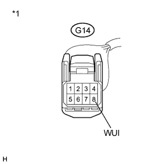
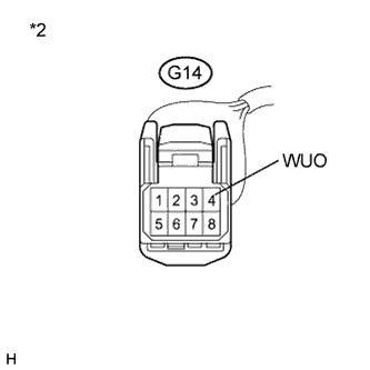
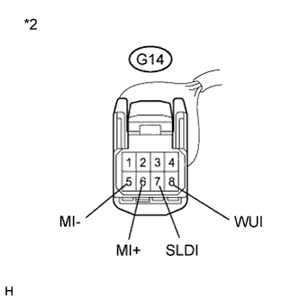
Text in Illustration *1 Front view of wire harness connector
(to Remote Touch)
Disconnect the G14 remote touch connector.
-
Measure the voltage according to the value(s) in the table below.
Standard Voltage Tester Connection Condition Specified Condition G14-8 (WUI) - Body ground Power switch on (ACC) 4.5 V or higher
NG
CHECK HARNESS AND CONNECTOR Click here
OK
REPLACE REMOTE OPERATION BOARD Click here
-
-
CHECK HARNESS AND CONNECTOR
-
Disconnect the G14 remote touch connector.
-
Disconnect the G6 display and navigation module display connector.
-
Measure the resistance according to the value(s) in the table below.
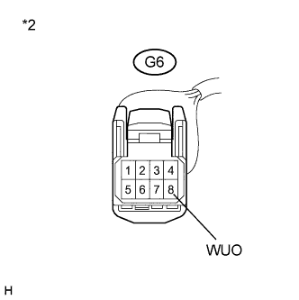
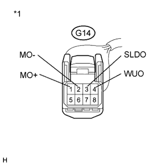
Standard Resistance Tester Connection Condition Specified Condition G14-8 (WUI) - G6-8 (WUO) Always Below 1 Ω G14-8 (WUI) - Body ground Always 10 kΩ or higher Text in Illustration *1 Front view of wire harness connector
(to Remote Touch)
*2 Front view of wire harness connector
(to Display and Navigation Module Display)
NG
REPAIR OR REPLACE HARNESS OR CONNECTOR
OK
REPLACE DISPLAY AND NAVIGATION MODULE DISPLAY Click here
-
-
CHECK MOST COMMUNICATION CONNECTORS
-
Check the MOST communication line connectors.
-
Check if the MOST communication line connector between the remote touch and radio receiver assembly have any connection problems Click here.
-
-
Display the "MOST Line Check" screen and check the result Click here.
Result Result Proceed to "NCON" is displayed for "AUDIO". A The screen cannot be changed to the "MOST Line Check" screen. B Tech Tips
When the malfunction in the MOST network is repaired, the screen cannot be changed to the "MOST Line Check" screen.
B
END
A
-
-
CHECK HARNESS AND CONNECTOR (WAKE-UP SIGNAL)
-
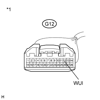
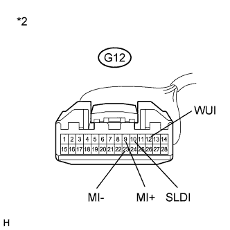
Text in Illustration *1 Front view of wire harness connector
(to Radio Receiver Assembly)
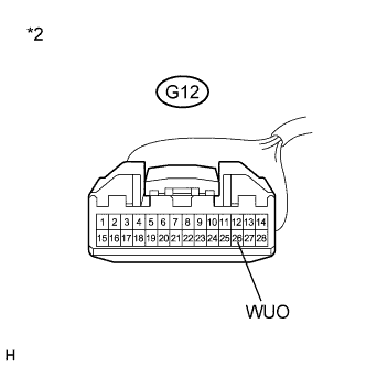
Disconnect the G12 radio receiver assembly connector.
-
Measure the voltage according to the value(s) in the table below.
Standard Voltage Tester Connection Condition Specified Condition G12-12 (WUI) - Body ground Power switch on (ACC) 4.5 V or higher
NG
CHECK HARNESS AND CONNECTOR Click here
OK
REPLACE RADIO RECEIVER ASSEMBLY Click here
-
-
CHECK HARNESS AND CONNECTOR
-
Disconnect the G12 radio receiver assembly connector.
-
Disconnect the G14 remote touch connector.
-
Measure the resistance according to the value(s) in the table below.
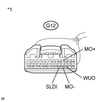
Standard Resistance Tester Connection Condition Specified Condition G12-12 (WUI) - G14-4 (WUO) Always Below 1 Ω G12-12 (WUI) - Body ground Always 10 kΩ or higher Text in Illustration *1 Front view of wire harness connector
(to Radio Receiver Assembly)
*2 Front view of wire harness connector
(to Remote Touch)
NG
REPAIR OR REPLACE HARNESS OR CONNECTOR
OK
REPLACE REMOTE OPERATION BOARD Click here
-
-
CHECK MOST COMMUNICATION CONNECTORS
-
Check the MOST communication line connectors.
-
Check if the MOST communication line connector between the radio receiver assembly and stereo component amplifier assembly have any connection problems Click here.
-
-
Display the "MOST Line Check" screen and check the result Click here.
Result Result Proceed to "NCON" is displayed for "AMP". A The screen cannot be changed to the "MOST Line Check" screen. B Tech Tips
When the malfunction in the MOST network is repaired, the screen cannot be changed to the "MOST Line Check" screen.
B
END
A
-
-
CHECK HARNESS AND CONNECTOR (WAKE-UP SIGNAL)
-
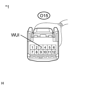
Text in Illustration *1 Front view of wire harness connector
(to Stereo Component Amplifier Assembly)
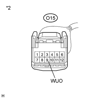
Disconnect the O15 stereo component amplifier assembly connector.
-
Measure the voltage according to the value(s) in the table below.
Standard Voltage Tester Connection Condition Specified Condition O15-3 (WUI) - Body ground Power switch on (ACC) 4.5 V or higher
NG
CHECK HARNESS AND CONNECTOR Click here
OK
REPLACE STEREO COMPONENT AMPLIFIER ASSEMBLY Click here
-
-
CHECK HARNESS AND CONNECTOR
-
Disconnect the O15 stereo component amplifier assembly connector.
-
Disconnect the G12 radio receiver assembly connector.
-
Measure the resistance according to the value(s) in the table below.
Standard Resistance Tester Connection Condition Specified Condition O15-3 (WUI) - G12-26 (WUO) Always Below 1 Ω O15-3 (WUI) - Body ground Always 10 kΩ or higher Text in Illustration *1 Front view of wire harness connector
(to Stereo Component Amplifier Assembly)
*2 Front view of wire harness connector
(to Radio Receiver Assembly)
NG
REPAIR OR REPLACE HARNESS OR CONNECTOR
OK
REPLACE RADIO RECEIVER ASSEMBLY Click here
-
-
CHECK MOST COMMUNICATION CONNECTORS
-
Check the MOST communication line connectors.
-
Check if the MOST communication line connector between the stereo component amplifier assembly and multi-display controller sub-assembly have any connection problems Click here.
-
-
Display the "MOST Line Check" screen and check the result Click here.
Result Result Proceed to "NCON" is displayed for "RSE". A The screen cannot be changed to the "MOST Line Check" screen. B Tech Tips
When the malfunction in the MOST network is repaired, the screen cannot be changed to the "MOST Line Check" screen.
B
END
A
-
-
CHECK HARNESS AND CONNECTOR (WAKE-UP SIGNAL)
-
Text in Illustration *1 Front view of wire harness connector
(to Multi-display Controller Sub-assembly)
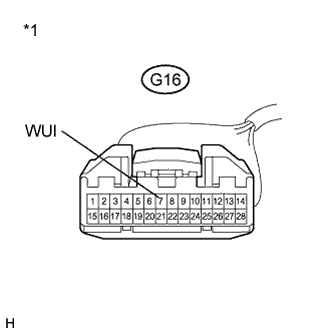
Disconnect the G16 multi-display controller sub-assembly connector.
-
Measure the voltage according to the value(s) in the table below.
Standard Voltage Tester Connection Condition Specified Condition G16-7 (WUI) - Body ground Power switch on (ACC) 4.5 V or higher
NG
CHECK HARNESS AND CONNECTOR Click here
OK
REPLACE MULTI-DISPLAY CONTROLLER SUB-ASSEMBLY Click here
-
-
CHECK HARNESS AND CONNECTOR
-
Disconnect the G16 multi-display controller sub-assembly connector.
-
Disconnect the O15 stereo component amplifier assembly connector.
-
Measure the resistance according to the value(s) in the table below.
Standard Resistance Tester Connection Condition Specified Condition G16-7 (WUI) - O15-9 (WUO) Always Below 1 Ω G16-7 (WUI) - Body ground Always 10 kΩ or higher Text in Illustration *1 Front view of wire harness connector
(to Multi-display Controller Sub-assembly)
*2 Front view of wire harness connector
(to Stereo Component Amplifier Assembly)
NG
REPAIR OR REPLACE HARNESS OR CONNECTOR
OK
REPLACE STEREO COMPONENT AMPLIFIER ASSEMBLY Click here
-
-
CHECK HARNESS AND CONNECTOR
-
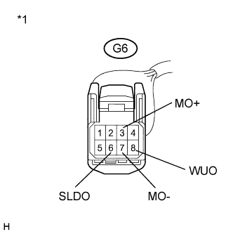
Disconnect the G6 display and navigation module display connector.
-
Disconnect the G14 remote touch connector.
-
Measure the resistance according to the value(s) in the table below.
Standard Resistance Tester Connection Condition Specified Condition G6-3 (MO+) - G14-6 (MI+) Always Below 1 Ω G6-7 (MO-) - G14-5 (MI-) Always Below 1 Ω G6-6 (SLDO) - G14-7 (SLDI) Always Below 1 Ω G6-8 (WUO) - G14-8 (WUI) Always Below 1 Ω G6-3 (MO+) - Body ground Always 10 kΩ or higher G6-7 (MO-) - Body ground Always 10 kΩ or higher G6-6 (SLDO) - Body ground Always 10 kΩ or higher G6-8 (WUO) - Body ground Always 10 kΩ or higher Text in Illustration *1 Front view of wire harness connector
(to Display and Navigation Module Display)
*2 Front view of wire harness connector
(to Remote Touch)
NG
REPAIR OR REPLACE HARNESS OR CONNECTOR
OK
-
-
CHECK HARNESS AND CONNECTOR
-
Disconnect the G14 remote touch connector.
-
Disconnect the G12 radio receiver assembly connector.
-
Measure the resistance according to the value(s) in the table below.
Standard Resistance Tester Connection Condition Specified Condition G14-1 (MO+) - G12-9 (MI+) Always Below 1 Ω G14-2 (MO-) - G12-23 (MI-) Always Below 1 Ω G14-3 (SLDO) - G12-10 (SLDI) Always Below 1 Ω G14-4 (WUO) - G12-12 (WUI) Always Below 1 Ω G14-1 (MO+) - Body ground Always 10 kΩ or higher G14-2 (MO-) - Body ground Always 10 kΩ or higher G14-3 (SLDO) - Body ground Always 10 kΩ or higher G14-4 (WUO) - Body ground Always 10 kΩ or higher Text in Illustration *1 Front view of wire harness connector
(to Remote Touch)
*2 Front view of wire harness connector
(to Radio Receiver Assembly)
NG
REPAIR OR REPLACE HARNESS OR CONNECTOR
OK
-
-
CHECK HARNESS AND CONNECTOR
-
Disconnect the G12 radio receiver assembly connector.
-
Disconnect the O15 stereo component amplifier assembly connector.
-
Measure the resistance according to the value(s) in the table below.
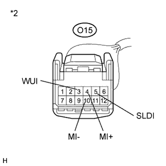
Standard Resistance Tester Connection Condition Specified Condition G12-11 (MO+) - O15-4 (MI+) Always Below 1 Ω G12-25 (MO-) - O15-10 (MI-) Always Below 1 Ω G12-24 (SLDI) - O15-5 (SLDI) Always Below 1 Ω G12-26 (WUO) - O15-3 (WUI) Always Below 1 Ω G12-11 (MO+) - Body ground Always 10 kΩ or higher G12-25 (MO-) - Body ground Always 10 kΩ or higher G12-24 (SLDI) - Body ground Always 10 kΩ or higher G12-26 (WUO) - Body ground Always 10 kΩ or higher Text in Illustration *1 Front view of wire harness connector
(to Radio Receiver Assembly)
*2 Front view of wire harness connector
(to Stereo Component Amplifier Assembly)
NG
REPAIR OR REPLACE HARNESS OR CONNECTOR
OK
-
-
CONFIRM MODEL
-
Choose the model to be inspected.
Result Result Proceed to w/o Rear Seat Entertainment System A w/ Rear Seat Entertainment System B
B
CHECK HARNESS AND CONNECTOR Click here
A
-
-
CHECK HARNESS AND CONNECTOR
-
Disconnect the O15 stereo component amplifier assembly connector.
-
Disconnect the G6 display and navigation module display connector.
-
Measure the resistance according to the value(s) in the table below.
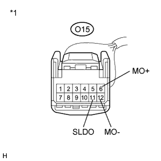
Standard Resistance Tester Connection Condition Specified Condition O15-6 (MO+) - G6-1 (MI+) Always Below 1 Ω O15-12 (MO-) - G6-5 (MI-) Always Below 1 Ω O15-11 (SLDO) - G6-2 (SLDI) Always Below 1 Ω O15-6 (MO+) - Body ground Always 10 kΩ or higher O15-12 (MO-) - Body ground Always 10 kΩ or higher O15-11 (SLDO) - Body ground Always 10 kΩ or higher Text in Illustration *1 Front view of wire harness connector
(to Stereo Component Amplifier Assembly)
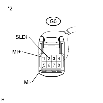
*2 Front view of wire harness connector
(to Display and Navigation Module Display)
NG
REPAIR OR REPLACE HARNESS OR CONNECTOR
OK
-
-
CHECK DTC
-
Clear the DTCs Click here.
-
Recheck for DTCs and check if the same DTC is output again.
Result Result Proceed to No DTCs are output. A DTC is output. B
B
REPLACE DISPLAY AND NAVIGATION MODULE DISPLAY Click here
A
USE SIMULATION METHOD TO CHECK Click here
-
-
CHECK HARNESS AND CONNECTOR
-
Disconnect the O15 stereo component amplifier assembly connector.
-
Disconnect the G16 multi-display controller sub-assembly connector.
-
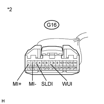
Measure the resistance according to the value(s) in the table below.
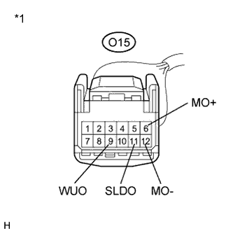
Standard Resistance Tester Connection Condition Specified Condition O15-6 (MO+) - G16-1 (MI+) Always Below 1 Ω O15-12 (MO-) - G16-2 (MI-) Always Below 1 Ω O15-11 (SLDO) - G16-3 (SLDI) Always Below 1 Ω O15-9 (WUO) - G16-7 (WUI) Always Below 1 Ω O15-6 (MO+) - Body ground Always 10 kΩ or higher O15-12 (MO-) - Body ground Always 10 kΩ or higher O15-11 (SLDO) - Body ground Always 10 kΩ or higher O15-9 (WUO) - Body ground Always 10 kΩ or higher Text in Illustration *1 Front view of wire harness connector
(to Stereo Component Amplifier Assembly)
*2 Front view of wire harness connector
(to Multi-display Controller Sub-assembly)
NG
REPAIR OR REPLACE HARNESS OR CONNECTOR
OK
-
-
CHECK HARNESS AND CONNECTOR
-
Disconnect the G16 multi-display controller sub-assembly connector.
-
Disconnect the G6 display and navigation module display connector.
-
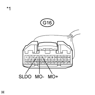
Measure the resistance according to the value(s) in the table below.
Standard Resistance Tester Connection Condition Specified Condition G16-6 (MO+) - G6-1 (MI+) Always Below 1 Ω G16-5 (MO-) - G6-5 (MI-) Always Below 1 Ω G16-4 (SLDO) - G6-2 (SLDI) Always Below 1 Ω G16-6 (MO+) - Body ground Always 10 kΩ or higher G16-5 (MO-) - Body ground Always 10 kΩ or higher G16-4 (SLDO) - Body ground Always 10 kΩ or higher Text in Illustration *1 Front view of wire harness connector
(to Multi-display Controller Sub-assembly)
*2 Front view of wire harness connector
(to Display and Navigation Module Display)
NG
REPAIR OR REPLACE HARNESS OR CONNECTOR
OK
-
-
CHECK DTC
-
Clear the DTCs Click here.
-
Recheck for DTCs and check if the same DTC is output again.
Result Result Proceed to No DTCs are output. A DTC is output. B
B
REPLACE DISPLAY AND NAVIGATION MODULE DISPLAY Click here
A
USE SIMULATION METHOD TO CHECK Click here
-