NAVIGATION SYSTEM (for DVD) Switch Lights of Remote Touch do not Illuminate
DESCRIPTION
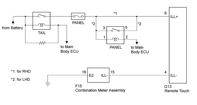
Power is supplied to the remote touch illumination when the light control switch is in the tail or head position.
Tech Tips
Only the "MAP/VOICE" and "MENU" switches on the remote touch illuminate.
WIRING DIAGRAM
INSPECTION PROCEDURE
PROCEDURE
-
CONFIRM SYMPTOMS
-
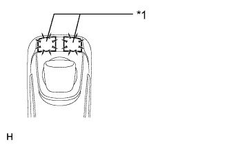
Text in Illustration *1 Switch Illumination Perform the following settings and check the switch illumination again.
-
When the vehicle is in a bright area, move to a dark area.
Tech Tips
When the vehicle is in a bright area, the switch illumination may not turn on due to the automatic dimmer function.
-
Set the rheostat to the maximum brightness.
Tech Tips
If the brightness of the rheostat is set to low, switch illumination may not be recognized even when the switch illumination turns on.
-
If the light control switch is in the AUTO position, turn the switch to the tail or head position.
Tech Tips
If the light control switch is in the AUTO position, the switch illumination will not turn on unless the surrounding area is dark.
OK Switch illumination turns on.
-
NG 
REMOTE TOUCH SELF CHECK (SWITCH ILLUMINATION CHECK)) Click here
OK 
END
-
-
REMOTE TOUCH SELF CHECK (SWITCH ILLUMINATION CHECK))
-
Activate self check mode Click here.
-
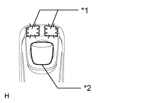
Text in Illustration *1 Switch Illumination *2 Switch Knob Check switch illumination.
-
Move the remote touch switch knob from the lower left to the upper right to check that the brightness of the switch illumination changes.
OK The switch illumination brightness changes according to the remote touch switch knob operation.
-
NG
REPLACE INTEGRATION PANEL SUB-ASSEMBLY Click here
OK 
-
-
CHECK HARNESS AND CONNECTOR
-
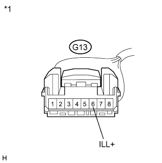
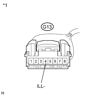
Text in Illustration *1 Front view of wire harness connector
(to Remote Touch)
Disconnect the remote touch connector.
-
Measure the voltage according to the value(s) in the table below.
Standard Voltage Tester Connection Condition Specified Condition G13-6 (ILL+) - Body ground Light control switch in tail or head 11 to 14 V
NG 
REPAIR OR REPLACE HARNESS OR CONNECTOR
OK
-
-
CHECK HARNESS AND CONNECTOR (REMOTE TOUCH - COMBINATION METER ASSEMBLY)
-
Disconnect the remote touch connector.
-
Disconnect the combination meter assembly connector.
-
Measure the resistance according to the value(s) in the table below.
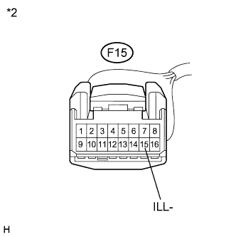
Standard Resistance Tester Connection Condition Specified Condition G13-4 (ILL-) - F15-15 (ILL-) Always Below 1 Ω G13-4 (ILL-) - Body ground Always 10 kΩ or higher Text in Illustration *1 Front view of wire harness connector
(to Remote Touch)
*2 Front view of wire harness connector
(to Combination Meter Assembly)
NG
REPAIR OR REPLACE HARNESS OR CONNECTOR
OK
REPLACE REMOTE TOUCH (REMOTE OPERATION BOARD)
-
-
REPLACE REMOTE TOUCH (REMOTE OPERATION BOARD)
-
Replace the remote touch (remote operation board) Click here.
-
Check if the switch illumination turns on.
OK The switch illumination turns on when the light control switch is in the tail or head position.
NG
GO TO METER / GAUGE SYSTEM Click here
OK
END
-
-
REPLACE INTEGRATION PANEL SUB-ASSEMBLY
-
Replace the integration panel sub-assembly Click here.
-
Check if the switch illumination turns on.
OK The switch illumination turns on when the light control switch is in the tail or head position.
NG
REPLACE REMOTE TOUCH (REMOTE OPERATION BOARD) Click here
OK
END
-