NAVIGATION SYSTEM (for DVD) TERMINALS OF ECU

-
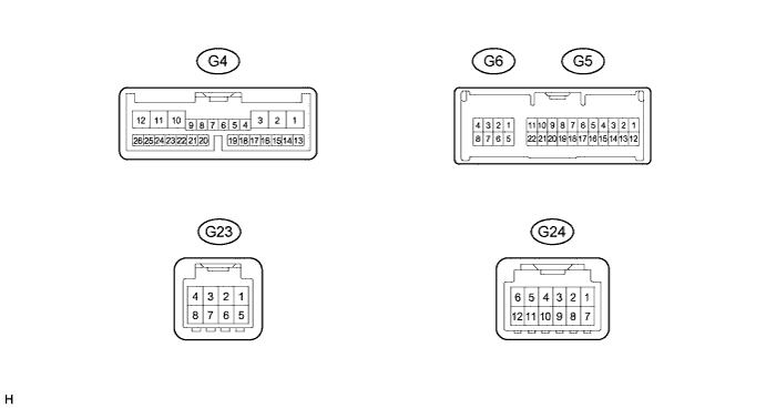
DISPLAY AND NAVIGATION MODULE DISPLAY
Terminal No.
(Symbol)
Wiring Color Terminal Description Condition Specified Condition G4-1 (+B1) - G4-10 (GND1) V - W-B Power source (Back-up) Always 11 to 14 V G4-2 (ACC) - G4-10 (GND1) W - W-B Power source (ACC) Power switch off Below 1 V Power switch on (ACC) 11 to 14 V G4-3 (IG) - G4-10 (GND1) SB - W-B Power source (IG) Power switch off Below 1 V Power switch on (IG) 11 to 14 V G4-4 (MACC) - G4-10 (GND1) B - W-B Microphone AMP power supply Power switch off Below 1 V Power switch on (IG) 4.5 to 5.5 V G4-5 (MIN+) - G4-10 (GND1) W - W-B Microphone voice signal See "Microphone&Voice Recognition Check" Click here
- G4-6 (MIN-) - Body ground R - Body ground Microphone voice signal See "Microphone&Voice Recognition Check" Click here
- G4-7 (SGND) - Body ground Shield - Body ground Shield ground Always Below 1 V G4-11 (ILL-) - G4-10 (GND1) G - W-B Illumination signal Light control switch: off Below 1 V Light control switch tail or head (Light intensity is not max. or min.) Pulse generation G4-12 (ILL+) - G4-10 (GND1) BR - W-B Illumination signal Light control switch: off Below 1 V Light control switch: tail or on 11 to 14 V G4-13 (TX+) B AVC-LAN communication signal - - G4-14 (TX-) P AVC-LAN communication signal - - G4-17 (PKB) - G4-10 (GND1) SB - W-B Parking brake signal See "Vehicle Signal Check Mode" Click here
- G4-18 (SPD) - G4-10 (GND1) L - W-B Vehicle speed signal See "Vehicle Signal Check Mode" Click here
- G4-20 (SNS2) - G4-10 (GND1) W - W-B Voice recognition and microphone connection detection signal Always Below 1 V G4-21 (CANH) L CAN communication signal - - G4-22 (CANL) R CAN communication signal - - G4-23 (SWG) - Body ground BR - Body ground Steering pad switch signal Always Below 1 V G4-24 (SW2) - G4-23 (SWG) B - BR Steering pad switch signal No switch pushed
→ MODE switch pushed
→ ON HOOK switch pushed
→ OFF HOOK switch pushed
→ VOICE switch pushed
4.44 to 5.43 V
→ 0.45 to 0.65 V
→ 1.19 to 1.49 V
→ 2.09 to 2.54 V
→ 3.2 to 3.88 V
G4-25 (SW1) - G4-23 (SWG) V - BR Steering pad switch signal No switch pushed
→ SEEK+ switch pushed
→ SEEK- switch pushed
→ VOL+ switch pushed
→ VOL- switch pushed
4.44 to 5.43 V
→ 0.45 to 0.65 V
→ 1.19 to 1.49 V
→ 2.09 to 2.54 V
→ 3.2 to 3.88 V
G5-1 (TX1+) P AVC-LAN communication signal - - G5-2 (TX1-) L AVC-LAN communication signal - - G5-9 (VV+) - G4-10 (GND1) BR - W-B Display signal DVD is playing A waveform synchronized with display signals is output.
(Refer to waveform 1)
G5-10 (NTSF) - G4-10 (GND1) G - W-B Display signal DVD is playing A waveform synchronized with display signals is output.
(Refer to waveform 2)
G5-11 (VMTF) - G4-10 (GND1) V - W-B Visual mute signal When image on display switches 3.5 V or higher → Below 1 V → 3.5 V or higher G5-12 (TX2+) G AVC-LAN communication signal - - G5-13 (TX2-) R AVC-LAN communication signal - - G5-20 (VV-) - G4-10 (GND1) Y - W-B Ground Always Below 1 V G5-21 (SGD1) - G4-10 (GND1) R - W-B Ground Always Below 1 V G5-22 (SLD1) - G4-10 (GND1) Shield - W-B Shield ground Always Below 1 V G6-1 (MI+) B MOST communication signal - - G6-2 (SLDI) - G4-10 (GND1) BR - W-B Shield ground Always Below 1 V G6-3 (MO+) B MOST communication signal - - G6-5 (MI-) W MOST communication signal - - G6-6 (SLDO) - G4-10 (GND1) GR - W-B Shield ground Always Below 1 V G6-7 (MO-) W MOST communication signal - - G6-8 (WUO) - G4-10 (GND1) L - W-B MOST communication wake up signal Power switch on (ACC) 4.5 V or higher Power switch off Below 1 V G23-1 (AGND) - Body ground Shield - Body ground Shield ground Always Below 1 V G23-3 (VAR+) - G23-7 (VA-) W - R Sound signal (Right) USB audio device playing (When stereo jack Adapter used) A waveform synchronized with sounds is output. G23-4 (VAL+) - G23-7 (VA-) B - R Sound signal (Left) USB audio device playing (When stereo jack Adapter used) A waveform synchronized with sounds is output. G23-7 (VA-) - G4-10 (GND1) R - W-B Sound signal ground Always Below 1 V G24-7 (GND) - Body ground P - Body ground Ground Always Below 1 V G24-9 (TXM+) Y AVC-LAN communication signal - - G24-10 (TXM-) W AVC-LAN communication signal - - G24-11 (ACC) - G4-10 (GND1) LG - W-B Accessory (ON) Power switch on (ACC) 11 to 14 V Power switch off Below 1 V G24-12 (+B) - G4-10 (GND1) BR - W-B Battery Power switch off 11 to 14 V
-
Reference (Oscilloscope waveform):
-
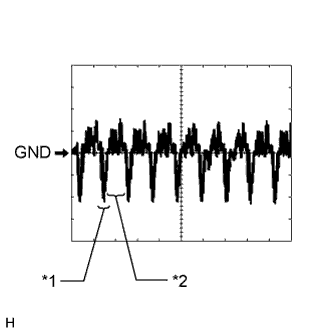
Waveform 1
Item Content Measurement Terminal G5-9 (VV+) - G4-10 (GND1) Measurement Setting 200 mV/DIV., 10 μs/DIV. Condition DVD is playing Note
The video waveform changes according to the image input from radio receiver assembly to display and navigation module display, but the synchronization signal does not change.
-

Text in Illustration *1 Synchronization Signal *2 Video Waveform *3 Synchronization Signal *4 Video Waveform Waveform 2
Item Content Measurement Terminal G5-10 (NTSF) - G4-10 (GND1) Measurement Setting 200 mV/DIV., 10 μs/DIV. Condition DVD is playing Note
The video waveform changes according to the image output from the display and navigation module display to the multi-display assembly, but the synchronization signal does not change.
-
-
-
MULTI-DISPLAY ASSEMBLY

Terminal No.
(Symbol)
Wiring Color Terminal Description Condition Specified Condition G2-2 (ILL) - G2-13 (GND1) G - W-B Illumination signal Light control switch: off Below 1 V G2-2 (ILL) - G2-13 (GND1) G - W-B Illumination signal Light control switch: tail or on 11 to 14 V G2-4 (NTSC) - G2-13 (GND1) G - W-B Display signal DVD is playing A waveform synchronized with display signals is output.
(Refer to waveform 3)
G2-6 (TX1+) Y AVC-LAN communication signal - - G2-7 (TX+) B AVC-LAN communication signal - - G2-11 (VMT1) - G2-13 (GND1) V - W-B Visual mute signal When image on display switches 3.5 V or higher → Below 1 V → 3.5 V or higher G2-12 (+B) - G2-13 (GND1) SB - W-B Battery Always 11 to 14 V G2-13 (GND1) - Body ground W-B - Body ground Ground Always Below 1 V G2-16 (SG) - Body ground R - Body ground Shield ground Always Below 1 V G2-18 (TX1-) W AVC-LAN communication signal - - G2-19 (TX-) P AVC-LAN communication signal - - G2-24 (ACC) - G2-13 (GND1) LG - W-B Power source (ACC) Power switch off Below 1 V Power switch on (ACC) 11 to 14 V
-
Reference (Oscilloscope waveform):
-
Text in Illustration *1 Synchronization Signal *2 Video Waveform Waveform 1
Item Content Measurement Terminal G2-4 (NTSC) - G2-13 (GND1) Measurement Setting 200 mV/DIV., 10 μs/DIV. Condition DVD is playing Note
The video waveform changes according to the image input from the display and navigation module display to the multi-display assembly, but the synchronization signal does not change.
-
-
-
NAVIGATION MODULE BOARD

Terminal No.
(Symbol)
Wiring Color Terminal Description Condition Specified Condition G17-1 (+B) - G17-5 (G) P - W-B Battery Always 11 to 14 V G17-3 (ACC) - G17-5 (G) R - W-B Power source (ACC) Power switch off Below 1 V Power switch on (ACC) 11 to 14 V G17-5 (G) - Body ground W-B - Body ground Ground Always Below 1 V -
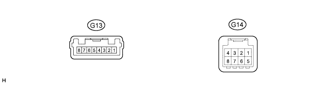
REMOTE TOUCH
Terminal No.
(Symbol)
Wiring Color Terminal Description Condition Specified Condition G13-1 (GND) - Body ground W-B - Body ground Ground Always Below 1 V G13-4 (ILL-) - G13-1 (GND) W - W-B Illumination signal Power switch on (IG) Light control switch off → tail or on (Light intensity is not max. or min.) Below 1 V → Pulse generation G13-6 (ILL+) - G13-1 (GND) BR - W-B Illumination signal Power switch on (IG) Light control switch off → tail or on Below 1 V → 11 to 14 V G13-7 (ACC) - G13-1 (GND) Y - W-B Power source (ACC) Power switch off Below 1 V Power switch on (ACC) 11 to 14 V G13-8 (+B) - G13-1 (GND) L - W-B Battery Always 11 to 14 V G14-1 (MO+) B MOST communication signal - - G14-2 (MO-) W MOST communication signal - - G14-3 (SLDO) - Body ground W - Body ground Shield ground Always Below 1 V G14-4 (WUO) - Body ground V - Body ground MOST communication wake up signal Power switch on (ACC) 4.5 V or higher Power switch off Below 1 V G14-5 (MI-) W MOST communication signal - - G14-6 (MI+) B MOST communication signal - - G14-7 (SLDI) - Body ground GR - Body ground Shield ground Always Below 1 V G14-8 (WUI) - Body ground L - Body ground MOST communication wake up signal Power switch on (ACC) 4.5 V or higher Power switch off Below 1 V -
RADIO RECEIVER ASSEMBLY Click here
-
COMBINATION METER MIRROR ECU Click here
-
STEREO COMPONENT AMPLIFIER ASSEMBLY Click here
-
PARKING ASSIST ECU Click here
-
PARKING ASSIST ECU (w/ Side Monitor System) Click here