REAR SEAT ENTERTAINMENT SYSTEM DVD Image Signal Circuit between Radio Receiver and Navigation ECU
DESCRIPTION
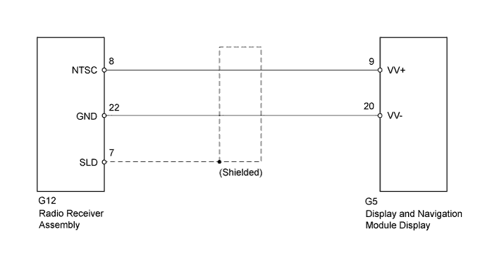
This is the DVD image signal circuit from the radio receiver assembly to the display and navigation module display.
WIRING DIAGRAM
INSPECTION PROCEDURE
Note
When replacing the display and navigation module display or telematics transceiver, perform vehicle contract setting (w/ G-BOOK System) Click here.
PROCEDURE
-
CHECK HARNESS AND CONNECTOR (RADIO RECEIVER - DISPLAY AND NAVIGATION MODULE DISPLAY)
-
Disconnect the radio receiver assembly connector.
-
Disconnect the display and navigation module display connector.
-
Measure the resistance according to the value(s) in the table below.
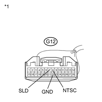
Standard Resistance Tester Connection Condition Specified Condition G12-8 (NTSC) - G5-9 (VV+) Always Below 1 Ω G12-22 (GND) - G5-20 (VV-) Always Below 1 Ω G12-8 (NTSC) - Body ground Always 10 kΩ or higher G12-22 (GND) - Body ground Always 10 kΩ or higher G12-7 (SLD) - Body ground Always 10 kΩ or higher Text in Illustration *1 Front view of wire harness connector
(to Radio Receiver Assembly)
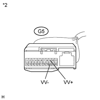
*2 Front view of wire harness connector
(to Display and Navigation Module Display)
NG 
REPAIR OR REPLACE HARNESS OR CONNECTOR
OK 
PROCEED TO NEXT SUSPECTED AREA SHOWN IN PROBLEM SYMPTOMS TABLE Click here
-