REAR SEAT ENTERTAINMENT SYSTEM TERMINALS OF ECU

-
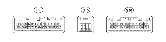
MULTI-DISPLAY CONTROLLER SUB-ASSEMBLY
Tech Tips
Check from the rear of the connector while it is connected to the multi-display controller sub-assembly.
Terminal No. (Symbol) Wiring Color Terminal Description Condition Specified Condition G16-1 (MI+) B MOST communication signal - - G16-2 (MI-) W MOST communication signal - - G16-3 (SLDI) - Body ground GR - Body ground Shield ground Always Below 1 V G16-4 (SLDO) - Body ground BR - Body ground Shield ground Always Below 1 V G16-5 (MO-) W MOST communication signal - - G16-6 (MO+) B MOST communication signal - - G16-7 (WUI) - G16-21 (GND) SB - BR MOST communication wake up signal Power switch on (ACC) 4.5 V or higher Power switch off Below 1 V G16-9 (GND1) - G16-21 (GND) P - BR Ground Always Below 1 V G16-10 (GND2) - G16-21 (GND) V - BR Ground Always Below 1 V G16-11 (VMTR) - G16-21 (GND) LG - BR Visual mute signal RSE is playing → Source is changed Above 3.5 V → Below 1 V G16-12 (PWR1) - G16-21 (GND) G - BR Power supply for television display assembly RH Power switch on (IG) 11 to 14 V G16-13 (PWR2) - G16-21 (GND) B - BR Power supply for television display assembly LH Power switch on (IG) 11 to 14 V G16-14 (+B) - G16-21 (GND) Y - BR Battery Always 11 to 14 V G16-15 (NTS4) - G16-21 (GND) BR - BR DVD image signal DVD is playing A waveform synchronized with display signals is input. G16-16 (SGN4) - Body ground Y - Body ground DVD image signal ground Always Below 1 V G16-21 (GND) - Body ground BR - Body ground Ground Always Below 1 V G16-22 (GND5) - Body ground W-B - Body ground Ground Always Below 1 V G16-23 (GND3) - Body ground R - Body ground Ground Always Below 1 V G16-24 (GND4) - Body ground W - Body ground Ground Always Below 1 V G16-25 (MD0) - G16-21 (GND) L - BR LH/RH display recognition signal Always Below 1 V G16-28 (+B1) - G16-21 (GND) SB - BR Battery Always 11 to 14 V P9-1 (NTS2) - G16-21 (GND) R - BR Display signal RSE is playing A waveform synchronized with display signals is output P9-2 (SGN2) - Body ground G - Body ground Display signal ground Always Below 1 V P9-3 (SLDB) - Body ground Shield - Body ground Shield ground Always Below 1 V P9-4 (VMT2) - G16-21 (GND) SB - BR Visual mute signal Display is operating Above 3.5 V P9-5 (TX2+) BR AVC-LAN communication signal - - P9-6 (TX2-) L AVC-LAN communication signal - - P9-7 (MUT1) - G16-21 (GND) W - BR Mute signal RSE is playing → Source is changed Above 3.5 V → Below 1 V P9-8 (MUT2) - G16-21 (GND) Y - BR Mute signal RSE is playing → Source is changed Above 3.5 V → Below 1 V P9-9 (HP1R) - G16-21 (GND) L - BR RSE sound signal RSE is playing Waveform synchronized with sound is output P9-10 (SG1) - G16-21 (GND) Shield - BR Shield ground Always Below 1 V P9-11 (HP1L) - G16-21 (GND) P - BR RSE sound signal RSE is playing Waveform synchronized with sound is output P9-13 (HP2R) - G16-21 (GND) V - BR RSE sound signal RSE is playing Waveform synchronized with sound is output P9-14 (SG2) - G16-21 (GND) Shield - BR Shield ground Always Below 1 V P9-15 (HP2L) - G16-21 (GND) SB - BR RSE sound signal RSE is playing Waveform synchronized with sound is output P9-17 (NTS1) - G16-21 (GND) BR - BR Display signal RSE is playing A waveform synchronized with display signals is output P9-18 (SGN1) - G16-21 (GND) Y - BR Display signal ground Always Below 1 V P9-19 (SLDA) - Body ground Shield - Body ground Shield ground Always Below 1 V P9-20 (VMT1) - G16-21 (GND) GR - BR Visual mute signal Display is operating Above 3.5 V P9-21 (TX1+) P AVC-LAN communication signal - - P9-22 (TX1-) LG AVC-LAN communication signal - - P9-23 (SLD1) - Body ground Shield - Body ground Shield ground Always Below 1 V P9-24 (R1+) - G16-21 (GND) BR - BR Sound signal RSE is playing A waveform synchronized with sound signals is output P9-25 (R1-) - G16-21 (GND) SB - BR Sound signal RSE is playing A waveform synchronized with sound signals is output P9-26 (L1+) - G16-21 (GND) LG - BR Sound signal RSE is playing A waveform synchronized with sound signals is output P9-27 (L1-) - G16-21 (GND) P - BR Sound signal RSE is playing A waveform synchronized with sound signals is output P9-28 (SLD2) - Body ground Shield - Body ground Shield ground Always Below 1 V P9-29 (R2+) - G16-21 (GND) W - BR Sound signal RSE is playing A waveform synchronized with sound signals is output P9-30 (R2-) - G16-21 (GND) R - BR Sound signal RSE is playing A waveform synchronized with sound signals is output P9-31 (L2+) - G16-21 (GND) G - BR Sound signal RSE is playing A waveform synchronized with sound signals is output P9-32 (L2-) - G16-21 (GND) B - BR Sound signal RSE is playing A waveform synchronized with sound signals is output G15-1 (R+) - G16-21 (GND) W - BR Sound signal External device is playing (when video terminal is used) A waveform synchronized with sound signals is input G15-2 (L+) - G16-21 (GND) B - BR Sound signal External device is playing (when video terminal is used) A waveform synchronized with sound signals is input G15-3 (SGN3) - G16-21 (GND) R - BR Sound signal ground Always Below 1 V G15-4 (SGN6) - Body ground Shield - Body ground Video terminal detective ground Always Below 1 V G15-5 (VD) - G16-21 (GND) R - BR Video signal External device is playing (when video terminal is used) A waveform synchronized with sound signals is input G15-6 (VG) - Body ground G - Body ground Video signal ground Always Below 1 V G15-7 (SGN5) - Body ground Shield - Body ground Shield ground Always Below 1 V G15-8 (ADPI) - G16-21 (GND) P - BR Video terminal connection detection signal External device is connecting Below 1 V -
TELEVISION DISPLAY ASSEMBLY LH

Tech Tips
Check from the rear of the connector while it is connected to the television display assembly LH.
Terminal No. (Symbol) Wiring Color Terminal Description Condition Specified Condition a17-1 (R2+) - a17-20 (GND) BR - V Sound signal RSE is playing A waveform synchronized with sound signals is input a17-2 (R2-) - a17-20 (GND) SB - V Sound signal RSE is playing A waveform synchronized with sound signals is input a17-3 (L2+) - a17-20 (GND) LG - V Sound signal RSE is playing A waveform synchronized with sound signals is input a17-4 (L2-) - a17-20 (GND) P - V Sound signal RSE is playing A waveform synchronized with sound signals is input a17-5 (MUT2) - a17-20 (GND) Y - V Mute signal RSE is playing → Source is changed Above 3.5 V → Below 1 V a17-7 (MUT1) - a17-20 (GND) SB - V Visual mute signal RSE is playing → Source is changed Above 3.5 V → Below 1 V a17-8 (TX2+) P AVC-LAN communication signal - - a17-9 (TX2-) L AVC-LAN communication signal - - a17-10 (NTSC) - a17-20 (GND) R - V Display signal RSE is playing A waveform synchronized with display signals is input a17-12 (PWR2) - a17-20 (GND) B - V Power supply for television display assembly LH Display is operating 11 to 14 V a17-19 (GND2) - Body ground W - Body ground Ground Always Below 1 V a17-20 (GND) - Body ground V - Body ground Ground Always Below 1 V a17-22 (SGN2) - Body ground G - Body ground Display signal ground Always Below 1 V -
TELEVISION DISPLAY ASSEMBLY RH

Tech Tips
Check from the rear of the connector while it is connected to the television display assembly RH.
Terminal No. (Symbol) Wiring Color Terminal Description Condition Specified Condition Z21-1 (R1+) - Z21-20 (G) BR - V Sound signal RSE is playing A waveform synchronized with sound signals is input Z21-2 (R1-) - Z21-20 (G) SB - V Sound signal RSE is playing A waveform synchronized with sound signals is input Z21-3 (L1+) - Z21-20 (G) LG - V Sound signal RSE is playing A waveform synchronized with sound signals is input Z21-4 (L1-) - Z21-20 (G) P - V Sound signal RSE is playing A waveform synchronized with sound signals is input Z21-5 (MUTE) - Z21-20 (G) W - V Mute signal RSE is playing → Source is changed Above 3.5 V → Below 1 V Z21-6 (MD0) - Z21-20 (G) LG - V LH/RH display recognition signal Always Below 1 V Z21-7 (VMTR) - Z21-20 (G) GR - V Visual mute signal RSE is playing → Source is changed Above 3.5 V → Below 1 V Z21-8 (TX1+) P AVC-LAN communication signal - - Z21-9 (TX1-) L AVC-LAN communication signal - - Z21-10 (VV1+) - Z21-20 (G) BR - V Display signal RSE is playing A waveform synchronized with display signals is input Z21-12 (PWR1) - Z21-20 (G) G - V Power supply for television display assembly RH Display is operating 11 to 14 V Z21-19 (G1) - Body ground R - Body ground Ground Always Below 1 V Z21-20 (G) - Body ground V - Body ground Ground Always Below 1 V Z21-22 (VV1-) - Body ground Y - Body ground Display signal ground Always Below 1 V -
RADIO RECEIVER ASSEMBLY Click here
-
DISPLAY AND NAVIGATION MODULE DISPLAY Click here