AUDIO AND VISUAL SYSTEM (w/o Navigation System) Multi-media Interface ECU Power Source Circuit
DESCRIPTION
This circuit provides power to the multi-media interface ECU.
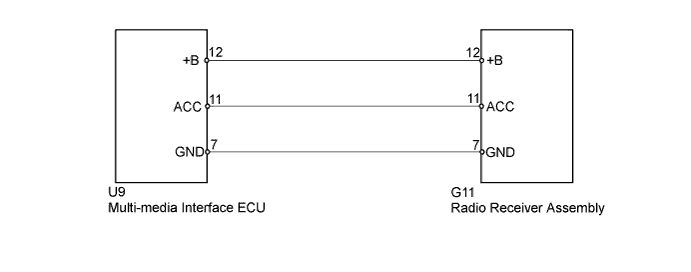
WIRING DIAGRAM
INSPECTION PROCEDURE
PROCEDURE
-
INSPECT MULTI-MEDIA INTERFACE ECU
-
Disconnect the multi-media interface ECU connector.
-
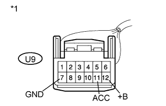
Text in Illustration *1 Front view of wire harness connector
(to Multi-media Interface ECU)
Measure the voltage according to the value(s) in the table below.
Standard Voltage Tester Connection Condition Specified Condition U9-12 (+B) - U9-7 (GND) Always 11 to 14 V U9-11 (ACC) - U9-7 (GND) Power switch on (ACC) 11 to 14 V
NG 
CHECK HARNESS AND CONNECTOR Click here
OK 
PROCEED TO NEXT SUSPECTED AREA SHOWN IN PROBLEM SYMPTOMS TABLE Click here
-
-
CHECK HARNESS AND CONNECTOR
-
Disconnect the radio receiver assembly connector.
-
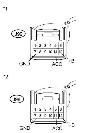
Text in Illustration *1 Front view of wire harness connector
(to Multi-media Interface ECU)
*2 Front view of wire harness connector
(to Radio Receiver Assembly)
Measure the resistance according to the value(s) in the table below.
Standard Resistance Tester Connection Condition Specified Condition U9-11 (ACC) - G11-11 (ACC) Always Below 1 Ω U9-12 (+B) - G11-12 (+B) Always Below 1 Ω U9-7 (GND) - G11-7 (GND) Always Below 1 Ω U9-11 (ACC) - Body ground Always 10 kΩ or higher U9-12 (B+) - Body ground Always 10 kΩ or higher U9-7 (GND) - Body ground Always 10 kΩ or higher
NG 
REPAIR OR REPLACE HARNESS OR CONNECTOR
OK
PROCEED TO NEXT SUSPECTED AREA SHOWN IN PROBLEM SYMPTOMS TABLE Click here
-