AUDIO AND VISUAL SYSTEM (w/o Navigation System) Dimmer Signal Circuit
DESCRIPTION
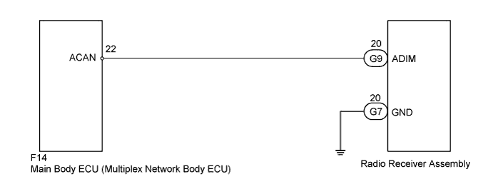
The radio receiver assembly uses this circuit to communicate with the main body ECU (multiplex network body ECU) via a direct line. The main body ECU (multiplex network body ECU) uses this circuit to send an auto dimmer signal to the radio receiver assembly. The main body ECU (multiplex network body ECU) detects the position of the light control switch according to the resistance. When the light control switch is set to the head/tail position, the resistance between the head/tail terminal and body ground is below 1Ω. When the light control switch is set to the head/tail position, the main body ECU (multiplex network body ECU) sends an auto dimmer signal to the radio receiver assembly. When the radio receiver assembly receives an auto dimmer signal from the main body ECU (multiplex network body ECU), the radio receiver assembly causes instrument panel illumination.
WIRING DIAGRAM
INSPECTION PROCEDURE
PROCEDURE
-
INSPECT MAIN BODY ECU (MULTIPLEX NETWORK BODY ECU)
-
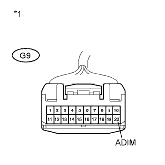
Text in Illustration *1 Front view of wire harness connector
(to Radio Receiver Assembly)
Disconnect the radio receiver assembly connector.
-
Measure the voltage according to the value(s) in the table below.
Standard Voltage Tester Connection Condition Specified Condition G9-20 (ADIM) - Body ground Power switch on (IG), automatic light control sensor covered by hand, and light control switch tail or head position 11 to 14 V
NG 
CHECK HARNESS AND CONNECTOR Click here
OK 
-
-
INSPECT RADIO RECEIVER ASSEMBLY
-
Disconnect the radio receiver assembly connector.
-
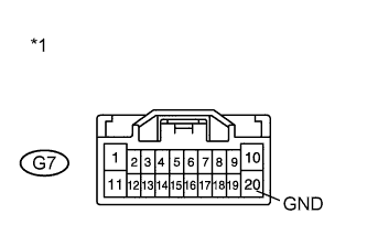
Text in Illustration *1 Front view of wire harness connector
(to Radio Receiver Assembly)
Measure the resistance according to the value(s) in the table below
Standard Resistance Tester Connection Condition Specified Condition G7-20 (GND) - Body ground Always Below 1 Ω
NG 
REPAIR OR REPLACE HARNESS OR CONNECTOR
OK 
REPLACE RADIO RECEIVER ASSEMBLY Click here
-
-
CHECK HARNESS AND CONNECTOR
-
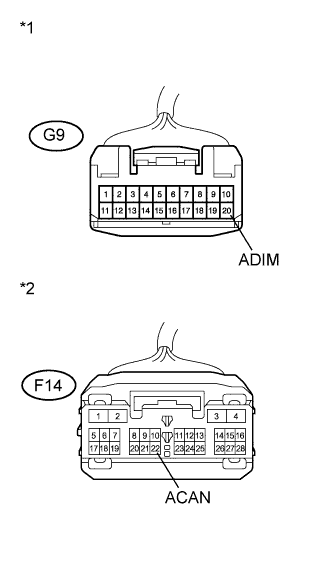
Text in Illustration *1 Front view of wire harness connector
(to Radio Receiver Assembly)
*2 Front view of wire harness connector
(to Main Body ECU (Multiplex Network Body ECU))
Disconnect the radio receiver assembly and main body ECU (multiplex network body ECU) connectors.
-
Measure the resistance according to the value(s) in the table below.
Standard Resistance Tester Connection Condition Specified Condition F14-22 (ACAN) - G9-20 (ADIM) Always Below 1 Ω G9-20 (ADIM) - Body ground Always 10 kΩ or higher
NG
REPAIR OR REPLACE HARNESS OR CONNECTOR
OK
REPLACE MAIN BODY ECU (MULTIPLEX NETWORK BODY ECU) Click here
-