AUDIO AND VISUAL SYSTEM (w/o Navigation System) Mute Signal Circuit between Radio Receiver and Multi-media Interface ECU
DESCRIPTION
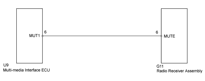
The multi-media interface ECU sends a mute signal to the radio receiver assembly.
The radio receiver assembly controls the volume according to the MUTE signal from the multi-media interface ECU.
The MUTE signal is sent to reduce noise and popping sounds generated when switching modes.
If there is an open in the circuit, noise can be heard from the speakers when changing the sound source.
If there is a short in the circuit, even though the radio receiver assembly is functioning, no sound, or only an extremely faint sound, can be heard.
WIRING DIAGRAM
INSPECTION PROCEDURE
PROCEDURE
-
INSPECT RADIO RECEIVER ASSEMBLY
-
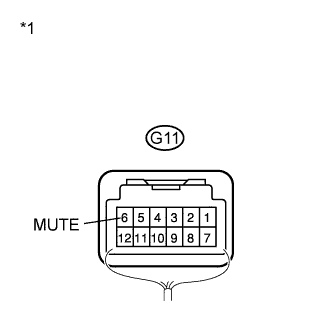
Text in Illustration *1 Component with harness connected
(Radio Receiver Assembly)
Measure the voltage according to the value(s) in the table below.
Standard Voltage Tester Connection Condition Specified Condition G11-6 (MUTE) - Body ground Power switch on (ACC), USB audio system is playing → Mode is changing Above 2.5 V → Below 0.5 V
NG 
CHECK HARNESS AND CONNECTOR (RADIO RECEIVER ASSEMBLY - MULTI-MEDIA INTERFACE ECU) Click here
OK 
PROCEED TO NEXT SUSPECTED AREA SHOWN IN PROBLEM SYMPTOMS TABLE Click here
-
-
CHECK HARNESS AND CONNECTOR (RADIO RECEIVER ASSEMBLY - MULTI-MEDIA INTERFACE ECU)
-
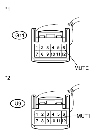
Text in Illustration *1 Front view of wire harness connector
(to Radio Receiver Assembly)
*2 Front view of wire harness connector
(to Multi-media Interface ECU)
Disconnect the radio receiver assembly and multi-media interface ECU connectors.
-
Measure the resistance according to the value(s) in the table below.
Standard Resistance Tester Connection Condition Specified Condition G11-6 (MUTE) - U9-6 (MUT1) Always Below 1 Ω G11-6 (MUTE) - Body ground Always 10 kΩ or higher
NG 
REPAIR OR REPLACE HARNESS OR CONNECTOR
OK 
-
-
INSPECT MULTI-MEDIA INTERFACE ECU
-
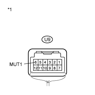
Text in Illustration *1 Component with harness connected
(Multi-media Interface ECU)
Reconnect the multi-media interface ECU connector.
-
Measure the voltage according to the value(s) in the table below.
Standard Voltage Tester Connection Condition Specified Condition U9-6 (MUT1) - Body ground Power switch on (ACC) Above 2.5 V
NG
REPLACE MULTI-MEDIA INTERFACE ECU Click here
OK
REPLACE RADIO RECEIVER ASSEMBLY Click here
-