AUDIO AND VISUAL SYSTEM (w/o Navigation System) Cellular Phone Voice Circuit between Radio Receiver and Stereo Component Amplifier
DESCRIPTION
This circuit is used when an incoming cellular phone voice in the "Bluetooth" hands-free system is received.
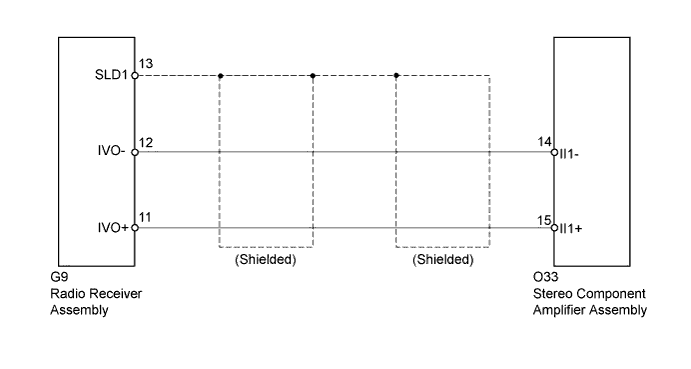
WIRING DIAGRAM
INSPECTION PROCEDURE
PROCEDURE
-
CHECK HARNESS AND CONNECTOR
-
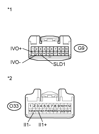
Text in Illustration *1 Front view of wire harness connector
(to Radio Receiver Assembly)
*2 Front view of wire harness connector
(to Stereo Component Amplifier Assembly)
Disconnect the radio receiver assembly and stereo component amplifier assembly connectors.
-
Measure the resistance according to the value(s) in the table below.
Standard Resistance Tester Connection Condition Specified Condition G9-11 (IVO+) - O33-15 (II1+) Always Below 1 Ω G9-12 (IVO-) - O33-14 (II1-) Always Below 1 Ω G9-11 (IVO+) - Body ground Always 10 kΩ or higher G9-12 (IVO-) - Body ground Always 10 kΩ or higher G9-13 (SLD1) - Body ground Always 10 kΩ or higher
NG 
REPAIR OR REPLACE HARNESS OR CONNECTOR
OK 
PROCEED TO NEXT SUSPECTED AREA SHOWN IN PROBLEM SYMPTOMS TABLE Click here
-