QUARTER WINDOW GLASS REMOVAL

Tech Tips
-
The quarter window assembly can be reused. If any clip of the quarter window assembly is broken, use butyl tape to support the glass until the applied adhesive hardens when reinstalling the quarter window assembly.
-
Use the same procedure for the RH side and LH side.
-
The procedure listed below is for the LH side.
-
PRECAUTION (w/ Navigation System for HDD)
Note
After the power switch is turned off, the display and navigation module display (HDD navigation system) records various types of memory and settings. As a result, after turning the power switch off, make sure to wait for the time specified in the following table before disconnecting the cable from the negative (-) battery terminal.
Waiting Time before Disconnecting Cable from Negative (-) Battery Terminal Specification Waiting Time w/o Telematics transceiver 60 sec. w/ Telematics transceiver 120 sec. -
REMOVE REAR DECK FLOOR BOX
-

Remove the 3 clips and the rear deck floor box.
-
-
DISCONNECT CABLE FROM NEGATIVE BATTERY TERMINAL
-
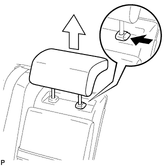
REMOVE REAR SEAT HEADREST ASSEMBLY LH (for LH Side)
-
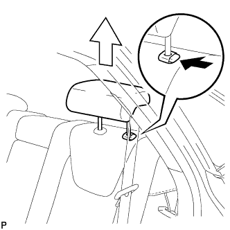
Press the headrest support button and pull up the headrest as shown in the illustration.
-
-
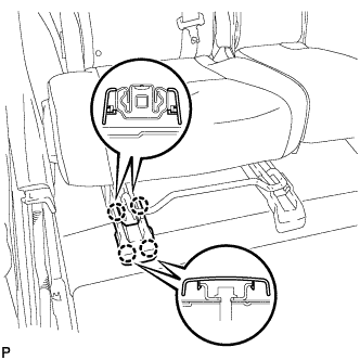
REMOVE REAR SEAT OUTER TRACK BRACKET COVER LH (for LH Side)
-
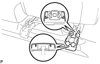
Disengage the 4 claws and remove the rear seat outer track bracket cover LH.
-
-
REMOVE REAR SEAT INNER TRACK BRACKET COVER LH (for LH Side)
-
Disengage the 4 claws and remove the rear seat inner track bracket cover LH.
-
-
DISCONNECT REAR SEAT LOCK CABLE ASSEMBLY LH (for LH Side)
-
Remove the 4 clips.
-
Remove the bolt.
-
Disengage the guide and disconnect the No. 1 fold seat stopper band assembly.
-
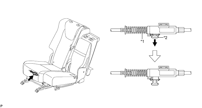
Pull down the adjuster lock piece to release the lock as shown in the illustration.
Text in Illustration *1 Adjuster Spring *2 Lock Piece -
Text in Illustration *1 Protective Tape Using a screwdriver wrapped with protective tape, disconnect the No. 2 reclining control cable as shown in the illustration.
-
Remove the rear seat reclining control cable from the cover as shown in the illustration.
-
Lift up the seat track adjusting handle to the uppermost position and hold the handle in this position as shown in the illustration.
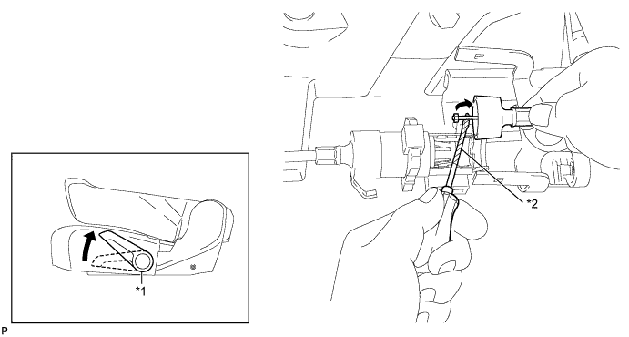
Text in Illustration *1 Seat Track Adjusting Handle *2 Protective Tape -
Using a screwdriver wrapped with protective tape, disconnect the No. 2 rear seat reclining control cable as shown in the illustration.
-
Using a screwdriver wrapped with protective tape, disconnect the rear seat lock cable assembly LH as shown in the illustration.
Text in Illustration *1 Protective Tape -
When replacing the rear seat assembly LH or No. 2 rear seat reclining control cable with a new one:
-
Cut portion A shown in the illustration to separate the rear seat assembly LH or No. 2 rear seat reclining control cable.
-
-
When replacing the rear seat lock cable assembly LH with a new one:
-
Cut portion A shown in the illustration to separate the rear seat lock assembly LH.
-
-
-
REMOVE REAR SEAT ASSEMBLY LH (for LH Side)
-
Disconnect the connector.
-
Remove the 3 bolts on the rear side of the seat.
-
Remove the 2 bolts on the front side of the seat and the rear seat assembly LH.
Note
Be careful not to damage the vehicle body.
-
-
REMOVE REAR SEAT HEADREST ASSEMBLY RH (for RH Side)
-
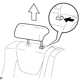
Press the headrest support button and pull up the headrest as shown in the illustration.
-
-
REMOVE REAR SEAT CENTER HEADREST ASSEMBLY (for RH Side)
-
Press the headrest support button and pull up the headrest as shown in the illustration.
-
-
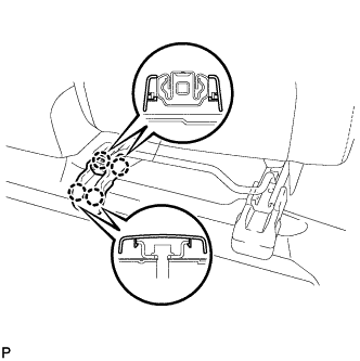
REMOVE REAR SEAT OUTER TRACK BRACKET COVER RH (for RH Side)
-
Disengage the 4 claws and remove the rear seat track bracket cover RH.
-
-
REMOVE REAR SEAT INNER TRACK BRACKET COVER RH (for RH Side)
-
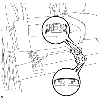
Disengage the 4 claws and remove the 4 rear seat track bracket cover RH.
-
-
DISCONNECT REAR SEAT LOCK CABLE ASSEMBLY RH (for RH Side)
-
Using a clip remover, remove the 2 clips and disconnect the rear seatback board sub-assembly.
-
Using a clip remover, remove the 3 clips and disconnect the rear seatback board carpet assembly RH.
-
Remove the bolt.
-
Disengage the guide and disconnect the No. 1 fold seat stopper band assembly.
-
Pull down the adjusters lock piece to release the lock as shown in the illustration.
Text in Illustration *1 Adjusters Spring *2 Lock Piece -
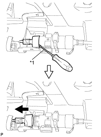
Text in Illustration *1 Protective Tape Using a screwdriver wrapped with protective tape, disconnect the No. 1 reclining control cable as shown in the illustration.
-
Remove the rear seat reclining control cable from the cover as shown in the illustration.
-
Lift up the seat track adjusting handle to the uppermost position and hold the handle in this position as shown in the illustration.
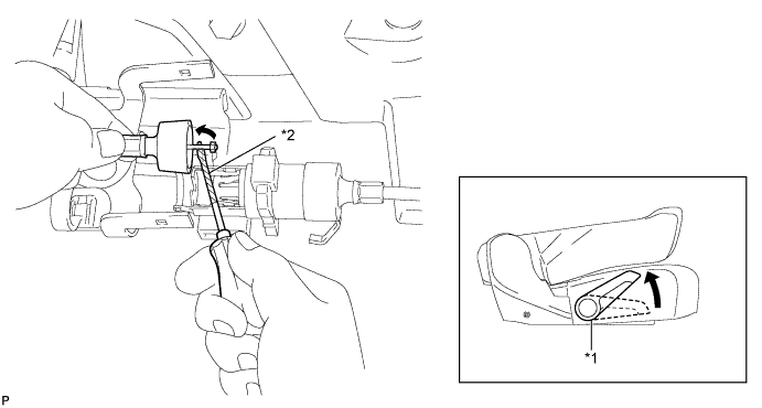
Text in Illustration *1 Seat Track Adjusting Handle *2 Protective Tape -
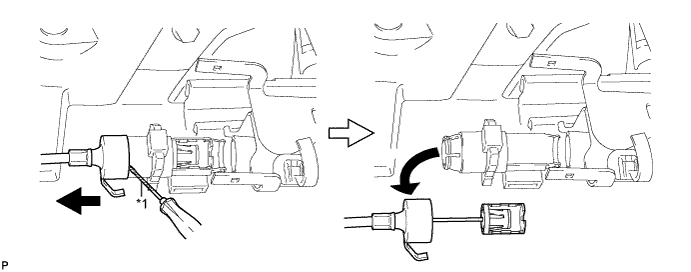
Using a screwdriver wrapped with protective tape, disconnect the No. 1 rear seat lock cable assembly as shown in the illustration.
-
Using a screwdriver wrapped with protective tape, disconnect the rear seat lock cable assembly RH as shown in the illustration.
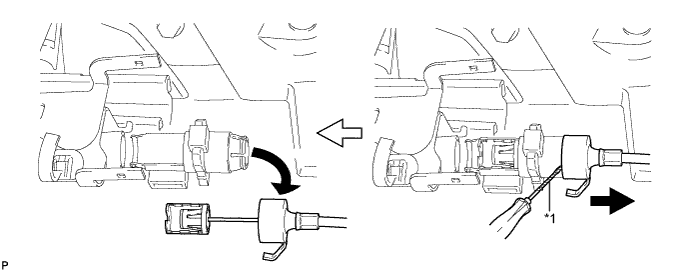
Text in Illustration *1 Protective Tape -
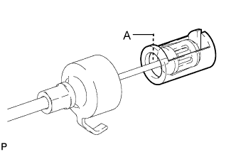
When replacing the rear seat assembly RH or rear seat reclining control cable with a new one:
-
Cut portion A shown in the illustration to separate the rear seat assembly RH or rear seat reclining control cable.
-
-
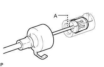
When replacing the rear seat lock cable assembly RH with a new one:
-
Cut portion A shown in the illustration to separate the rear seat lock assembly RH.
-
-
-
REMOVE REAR SEAT ASSEMBLY RH (for RH Side)
-
Disconnect the connector.
-
Remove the 3 bolts on the rear side of the seat.
-
Remove the 2 bolts on the front side of the seat and the rear seat assembly RH.
Note
Be careful not to damage the vehicle body.
-
-
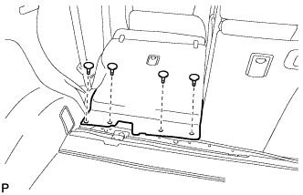
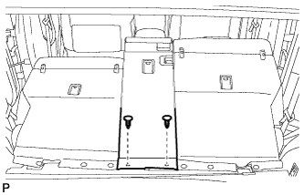
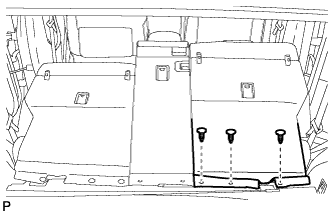
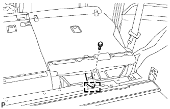
REMOVE DECK BOARD SUB-ASSEMBLY
-
Disengage the 3 fasteners as shown in the illustration.
-
for Compact Spare Tire:
-
Remove the 2 bolts and remove the deck board sub-assembly.
-
-
for Full Size Spare Tire:
-
Remove the 2 bolts and remove the deck board sub-assembly.
-
-
-
REMOVE SPARE WHEEL COVER ASSEMBLY (for Compact Spare Tire)
-
Remove the spare wheel cover assembly.
-
-
REMOVE NO. 4 REAR FLOOR BOARD (for Compact Spare Tire)
-
Disengage the 2 guides and remove the No. 4 rear floor board.
-
-
REMOVE NO. 4 REAR FLOOR BOARD (for Full Size Spare Tire)
-
Disengage the 2 guides and remove the No. 4 rear floor board.
-
-
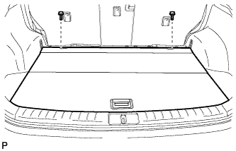
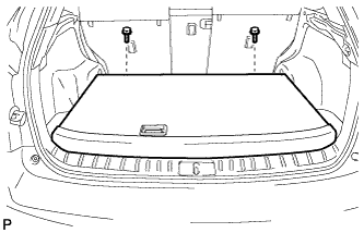
REMOVE TONNEAU COVER ASSEMBLY
-
Remove the tonneau cover assembly.
-
-
REMOVE DECK SIDE TRIM BOX (for Compact Spare Tire)
-
Remove the 2 clips and the deck side trim box LH.
-
-
REMOVE DECK SIDE TRIM BOX (for Full Size Spare Tire)
-
Remove the 3 clips and the deck side trim box LH.
-
-
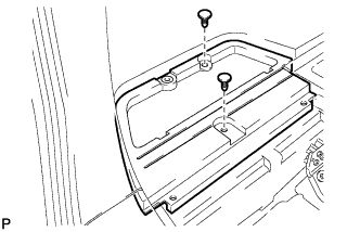
REMOVE FRONT DECK FLOOR BOX
-
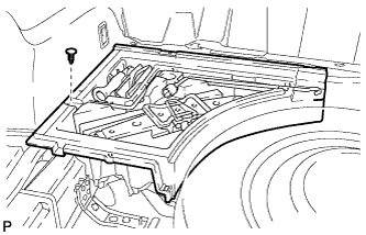
Remove the clip and the front deck floor box.
-
-
REMOVE REAR FLOOR FINISH PLATE
-
Disengage the 2 claws, 6 clips and 2 guides, and remove the rear floor finish plate.
-
-
REMOVE REAR FLOOR FINISH SIDE PLATE
-
Remove the clip.
-
Disengage the claw and 2 clips.
-
Disengage the guide and remove the rear floor finish side plate LH.
-
-
REMOVE REAR DOOR SCUFF PLATE
-
Disengage the 6 claws, 3 clips and guide, and remove the rear door scuff plate LH.
-
-
REMOVE REAR SEAT SIDE COVER
-
Remove the 2 clips.
-
Disengage the 2 claws and 3 clips, and remove the rear seat side cover LH.
Tech Tips
A part of the clip remains on the vehicle side.
-
-
REMOVE NO. 1 LUGGAGE COMPARTMENT TRIM HOOK (for LH Side)
-
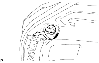
Remove the No. 1 luggage compartment trim hook as shown in the illustration.
-
-
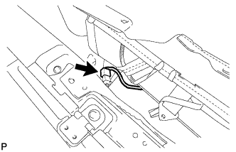
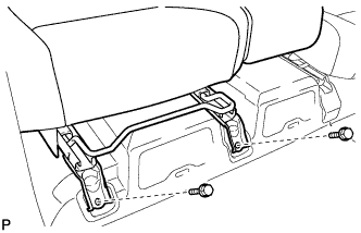
REMOVE ROPE HOOK ASSEMBLY (for LH Side)
-
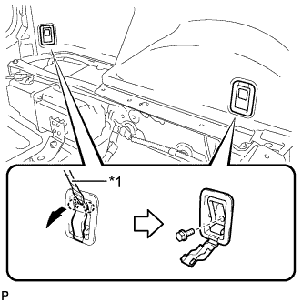
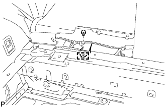
Text in Illustration *1 Protective Tape Using a screwdriver, disengage the 2 claws.
Tech Tips
Tape the screwdriver tip before use.
-
Remove the 2 bolts and the 2 rope hook assemblies.
-
-
REMOVE RECLINING REMOTE CONTROL BEZEL
-
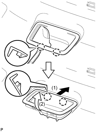
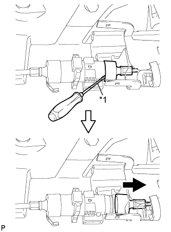
Using moulding remover A, disengage the 2 bottom claws of the reclining remote control bezel LH.
-
Lift the reclining remote control bezel LH as shown by the arrow (1) in the illustration.
-
Turn the reclining remote control bezel LH as shown by the arrow (2) in the illustration, then disengage the 2 upper claws and remove the bezel.
-
-
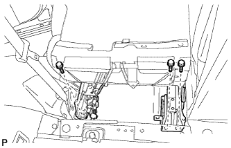
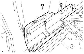
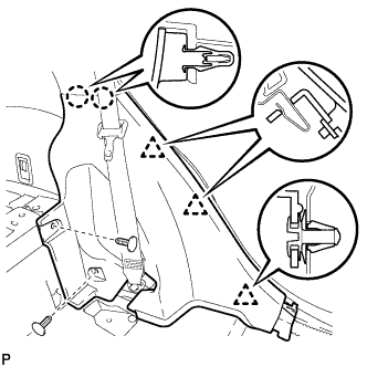
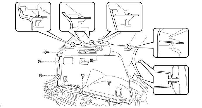
REMOVE DECK TRIM SIDE PANEL ASSEMBLY LH (for LH Side)
-
Remove the 2 screws.
-
Remove the 4 clips.
-
Disengage the 5 claws and 2 clips.
-
Disconnect each connector and remove the deck trim side panel assembly LH.
-
-
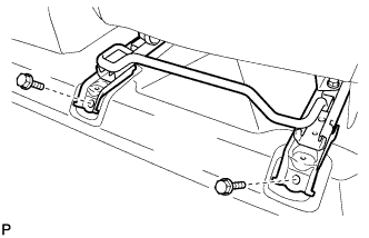
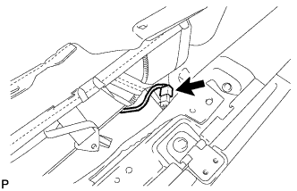
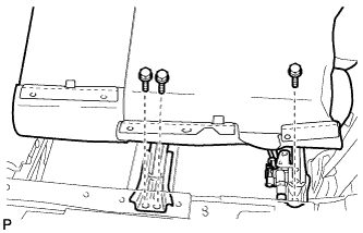
DISCONNECT REAR SEAT OUTER BELT ASSEMBLY
-
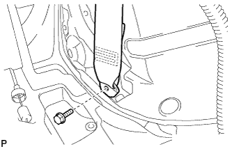
Remove the bolt and disconnect the floor end of the rear seat outer belt assembly.
-
-
REMOVE NO. 1 LUGGAGE COMPARTMENT TRIM HOOK (for RH Side)
-
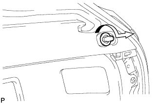
Remove the No. 1 luggage compartment trim hook as shown in the illustration.
-
-
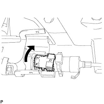
REMOVE HEIGHT CONTROL SWITCH (for RH Side)
-
w/ Air Suspension:
-
Remove the height control switch Click here.
-
-
-
REMOVE DECK TRIM SIDE PANEL ASSEMBLY RH (for RH Side)
-
Remove the 2 screws.
-
Remove the 5 clips.
-
Disengage the 5 claws and 2 clips.
-
Disconnect the connector and remove the deck trim side panel assembly RH.
-
-
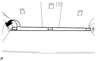
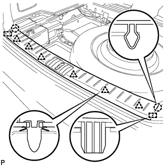
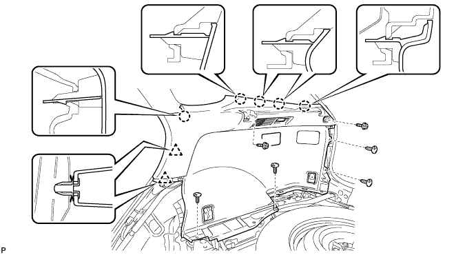
REMOVE ROOF SIDE INNER GARNISH ASSEMBLY
-
Disengage the 8 clips.
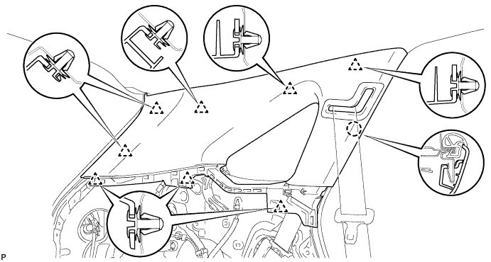
Tech Tips
A part of the clip remains on the vehicle side.
-
Pass the floor anchor of the rear seat outer seat belt assembly LH through the roof side inner garnish assembly LH and remove the roof side inner garnish assembly LH.
-
-
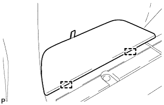
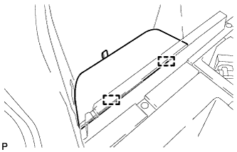
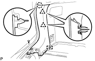
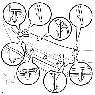
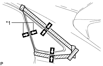
REMOVE QUARTER WINDOW ASSEMBLY
-
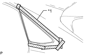
Text in Illustration *1 Protective Tape Apply protective tape to the outer surface of the vehicle body to prevent scratches.
-
Text in Illustration *1 Matchmark Place matchmarks on the quarter window assembly and vehicle body on the locations indicated in the illustration.
Tech Tips
Matchmarks are not necessary if the quarter window assembly is not going to be reused.
-
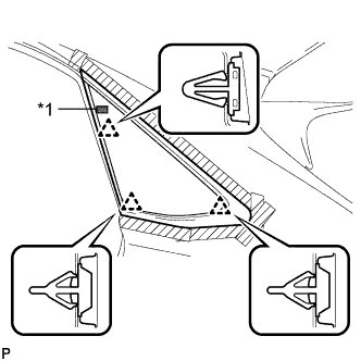
Text in Illustration *1 Piano Wire Pass a piano wire between the vehicle body and glass as shown in the illustration.
-
Tie both wire ends to wooden blocks or similar objects that can serve as handles.
Note
When separating the quarter window assembly from the vehicle, be careful not to damage the paint or interior and exterior ornaments.
-
Cut off the adhesive by pulling the piano wire around the quarter window assembly.
Note
Leave as much adhesive on the vehicle body as possible when cutting through the adhesive.
-
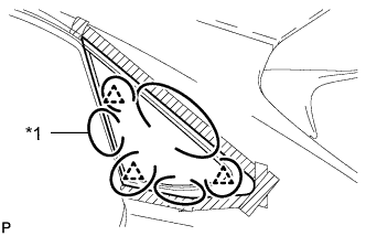
Text in Illustration *1 Double-sided Tape Using suction cups disengage the 3 clips and remove the glass.
Note
Be careful not to drop the glass.
-
-
CLEAN VEHICLE BODY
-
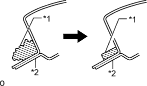
Text in Illustration *1 Adhesive *2 Vehicle Body Clean and shape the contact surfaces of the vehicle body.
-
Using a knife, cut away excess adhesive on the contact surfaces of the vehicle body as shown in the illustration.
Note
Be careful not to damage the vehicle body.
Tech Tips
Leave as much adhesive on the vehicle body as possible.
-
-
Clean the contact surfaces of the vehicle body with a piece of cloth saturated with cleaner.
Tech Tips
Even if all the adhesive has been removed, clean the vehicle body.
-