WINDOW DEFOGGER SYSTEM Rear Window Defogger System does not Operate
DESCRIPTION
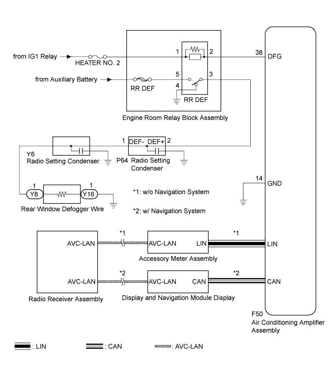
When the rear window defogger switch on the radio receiver assembly is pressed, the operation signal is transmitted to the air conditioning amplifier assembly through the AVC-LAN and LIN*1 or CAN*2 communication line. When the air conditioning amplifier assembly receives the signal, it turns on the RR DEF relay to operate the rear window defogger.
-
*1: w/o Navigation System
-
*2: w/ Navigation System
WIRING DIAGRAM
INSPECTION PROCEDURE
Note
-
Inspect the fuses for circuits related to this system before performing the following inspection procedure.
-
Since the window defogger system uses the AVC-LAN and LIN*1 or CAN*2 communication, first confirm that there is no malfunction in the AVC-LAN and LIN*1 or CAN*2 communication line. Refer to the How to Proceed with Troubleshooting procedure Click here.
-
*1: w/o Navigation System
-
*2: w/ Navigation System
PROCEDURE
-
CHECK AIR CONDITIONING SYSTEM
-
Check the air conditioning system.
Tech Tips
Both the window defogger system operation signal and air conditioning system operation signal are transmitted to the air conditioning amplifier assembly through same communication line.
OK The air conditioning system operates normally.
NG 
GO TO AIR CONDITIONING SYSTEM Click here
OK 
-
-
PERFORM ACTIVE TEST USING INTELLIGENT TESTER
-
Connect the intelligent tester to the DLC3.
-
Turn the power switch on (IG).
-
Turn the intelligent tester on.
-
Enter the following menus: Body / Air Conditioner / Active Test.
-
Perform the Active Test according to the display on the intelligent tester.
Air Conditioner (Air Conditioning Amplifier Assembly) Tester Display Test Part Control Range Diagnostic Note Defogger Relay (Rear) Rear window defogger OFF or ON - OK The window defogger system operates normally.
NG 
INSPECT RR DEF RELAY Click here
OK 
REPLACE RADIO RECEIVER ASSEMBLY Click here
-
-
INSPECT RR DEF RELAY
-
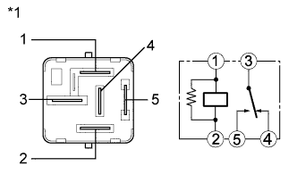
Text in Illustration *1 Component without harness connected
(RR DEF Relay)
Remove the RR DEF relay from the engine room relay block assembly.
-
Measure the resistance according to the value(s) in the table below.
Standard Resistance Tester Connection Condition Specified Condition 3 - 4 Auxiliary battery voltage applied between terminals 1 and 2 10 kΩ or higher 3 - 4 Auxiliary battery voltage not applied between terminals Below 1 Ω 3 - 5 Auxiliary battery voltage applied between terminals 1 and 2 Below 1 Ω 3 - 5 Auxiliary battery voltage not applied between terminals 10 kΩ or higher
NG
REPLACE RR DEF RELAY
OK
-
-
CHECK HARNESS AND CONNECTOR (RR DEF RELAY POWER SOURCE)
-
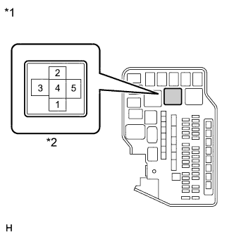
Text in Illustration *1 Front view of wire harness connector
(to RR DEF Relay)
*2 RR DEF Relay Terminal Measure the voltage according to the value(s) in the table below.
Standard Voltage Tester Connection Switch Condition Specified Condition Engine room relay block RR DEF relay terminal 1 - Body ground Power switch off Below 1 V Engine room relay block RR DEF relay terminal 1 - Body ground Power switch on (IG) 11 to 14 V
NG
REPAIR OR REPLACE HARNESS OR CONNECTOR
OK
-
-
CHECK HARNESS AND CONNECTOR (ENGINE ROOM RELAY BLOCK - AIR CONDITIONING AMPLIFIER)
-
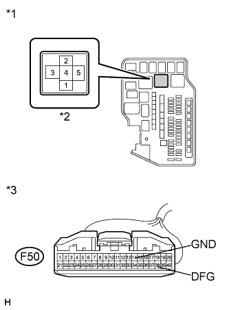
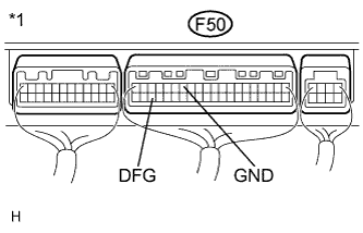
Text in Illustration *1 Front view of wire harness connector
(to RR DEF Relay)
*2 RR DEF Relay Terminal *3 Front view of wire harness connector
(to Air Conditioning Amplifier Assembly)
Disconnect the F50 connector.
-
Measure the resistance according to the value(s) in the table below.
Standard Resistance Tester Connection Condition Specified Condition Engine room relay block RR DEF relay terminal 2 - F50-38 (DFG) Always Below 1 Ω F50-14 (GND) - Body ground Always Below 1 Ω F50-38 (DFG) - Body ground Always 10 kΩ or higher
NG
REPAIR OR REPLACE HARNESS OR CONNECTOR
OK
-
-
INSPECT AIR CONDITIONING AMPLIFIER ASSEMBLY
-
Text in Illustration *1 Component without harness connected
(Air Conditioning Amplifier Assembly)
Install the RR DEF relay to the engine room relay block assembly.
-
Reconnect the F50 connector.
-
Measure the voltage according to the value(s) in the table below.
Standard Voltage Tester Connection Switch Condition Specified Condition F50-38 (DFG) - F50-14 (GND) Power switch on (IG), rear window defogger switch off 11 to 14 V F50-38 (DFG) - F50-14 (GND) Power switch on (IG), rear window defogger switch on Below 1 V
NG
REPLACE AIR CONDITIONING AMPLIFIER ASSEMBLY Click here
OK
-
-
CHECK HARNESS AND CONNECTOR (REAR WINDOW DEFOGGER POWER SOURCE)
-
Text in Illustration *1 Front view of wire harness connector
(to RR DEF Relay)
*2 RR DEF Relay Terminal Remove the RR DEF relay from the engine room relay block assembly.
-
Measure the voltage according to the value(s) in the table below.
Standard Voltage Tester Connection Switch Condition Specified Condition Engine room relay block RR DEF relay terminal 5 - Body ground Power switch off 11 to 14 V
NG
REPAIR OR REPLACE HARNESS OR CONNECTOR
OK
-
-
CHECK HARNESS AND CONNECTOR (RR DEF RELAY - RADIO SETTING CONDENSER)
-
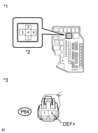
Text in Illustration *1 Front view of wire harness connector
(to RR DEF Relay)
*2 RR DEF Relay Terminal *3 Front view of wire harness connector
(to Radio Setting Condenser)
Disconnect the P64 connector.
-
Measure the resistance according to the value(s) in the table below.
Standard Resistance Tester Connection Switch Condition Specified Condition Engine room relay block RR DEF relay terminal 3 - P64-2 (DEF+) Always Below 1 Ω Engine room relay block RR DEF relay terminal 3 - Body ground Always 10 kΩ or higher P64-2 (DEF+) - Body ground Always 10 kΩ or higher
NG
REPAIR OR REPLACE HARNESS OR CONNECTOR
OK
-
-
REPLACE RADIO SETTING CONDENSER
-
Replace the radio setting condenser.
-
Check the rear window defogger operation.
OK The rear window defogger operated normally.
NG
CHECK HARNESS AND CONNECTOR (RADIO SETTING CONDENSER - REAR WINDOW DEFOGGER WIRE) Click here
OK
END (RADIO SETTING CONDENSER WAS DEFECTIVE)
-
-
CHECK HARNESS AND CONNECTOR (RADIO SETTING CONDENSER - REAR WINDOW DEFOGGER WIRE)
-
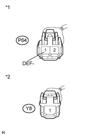
Text in Illustration *1 Front view of wire harness connector
(to Radio Setting Condenser)
*2 Front view of wire harness connector
(to Rear Window Defogger Wire)
Disconnect the P64 connector.
-
Disconnect the Y8 rear window defogger wire auxiliary battery side connector.
-
Measure the resistance according to the value(s) in the table below.
Standard Resistance Tester Connection Switch Condition Specified Condition P64-1 (DEF-) - Y8-1 Always Below 1 Ω P64-1 (DEF-) - Body ground Always 10 kΩ or higher Y8-1 - Body ground Always 10 kΩ or higher
NG
REPAIR OR REPLACE HARNESS OR CONNECTOR
OK
-
-
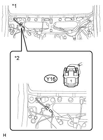
INSPECT BACK DOOR GLASS (REAR WINDOW DEFOGGER WIRE)
-
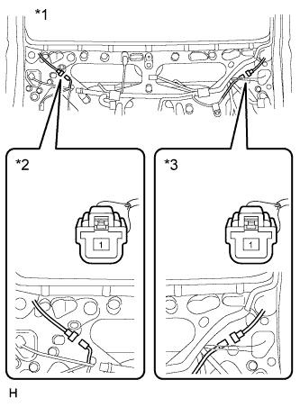
Text in Illustration *1 Component without harness connected
(Rear Window Defogger Wire (Back Door Glass))
*2 Body Ground Side *3 Auxiliary Battery Side Disconnect the Y16 rear window defogger wire body ground side connector.
-
Measure the resistance according to the value(s) in the table below.
Standard Resistance Tester Connection Switch Condition Specified Condition 1 - 1 Always Below 1 Ω
NG
REPAIR OR REPLACE BACK DOOR GLASS (REAR WINDOW DEFOGGER WIRE)
OK
-
-
CHECK HARNESS AND CONNECTOR (REAR WINDOW DEFOGGER WIRE - BODY GROUND)
-
Text in Illustration *1 Front view of wire harness connector
(Rear Window Defogger Wire (Back Door Glass))
*2 Body Ground Side Measure the resistance according to the value(s) in the table below.
Standard Resistance Tester Connection Switch Condition Specified Condition Y16-1 - Body ground Always Below 1 Ω
NG
REPAIR OR REPLACE HARNESS OR CONNECTOR
OK
REPLACE AIR CONDITIONING AMPLIFIER ASSEMBLY Click here
-