WINDSHIELD DEICER SYSTEM Windshield Deicer does not Operate
DESCRIPTION
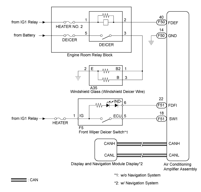
By operating the deicer switch while the power switch is on (IG), the windshield deicer can be activated. For vehicles with the navigation system, the operation signals are sent to the air conditioning amplifier assembly via CAN communication. For vehicles without the navigation system, the operation signals are sent directly from the front wiper deicer switch to the air conditioning amplifier assembly. The windshield deicer system is controlled by the air conditioning amplifier assembly. On receiving a deicer switch on signal, the air conditioning amplifier assembly turns on the DEICER relay for 15 minutes. If the air conditioning amplifier assembly receives a deicer switch off signal while the DEICER relay is on, it turns off the relay.
WIRING DIAGRAM
INSPECTION PROCEDURE
Note
Inspect the fuses for circuits related to this system before performing the following inspection procedure.
PROCEDURE
-
READ VALUE USING INTELLIGENT TESTER (Battery Voltage Lo Record)
-
Connect the intelligent tester to the DLC3.
-
Turn the power switch on (IG).
-
Turn the intelligent tester on.
-
Enter the following menus: Chassis / EMPS / Data List.
-
Read the Data List according to the display on the intelligent tester.
EMPS Tester Display Measurement item/Range Normal Condition Diagnostic Note Battery Voltage Lo Record Battery voltage reduction history/ Min.: 0 times, Max.: 65535 times 0 to 65535 - Result Result Proceed to Other then 0 (history record is present) A 0 (no history record is present) B
A 
GO TO CHARGING SYSTEM Click here
B 
-
-
PERFORM ACTIVE TEST USING INTELLIGENT TESTER (FRONT DEICER RELAY)
-
Enter the following menus: Body / Air Conditioner / Active Test.
-
Using the intelligent tester, perform the Active Test.
Air Conditioner Tester Display Test Part Control Range Diagnostic Note Deicer Relay (Front) Deicer relay ON / OFF - Result Result Proceed to Windshield deicer operates. (w/o Navigation System) A Windshield deicer operates. (w/ Navigation System) B Windshield deicer does not operate. C
B
GO TO AIR CONDITIONING SYSTEM Click here
C 
CHECK FRONT WIPER DEICER RELAY Click here
A
-
-
INSPECT FRONT WIPER DEICER SWITCH
-
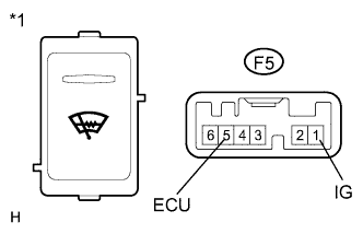
Text in Illustration *1 Component without harness connected
(Front Wiper Deicer Switch)
Remove the front wiper deicer switch Click here.
-
Measure the resistance according to the value(s) in the table below.
Standard Resistance Tester Connection Switch Condition Specified Condition F5-1 (IG) - F5-5 (ECU) Front wiper deicer switch on Below 1 Ω F5-1 (IG) - F5-5 (ECU) Front wiper deicer switch off 10 kΩ or higher
NG
REPLACE FRONT WIPER DEICER SWITCH Click here
OK
-
-
CHECK HARNESS AND CONNECTOR
-
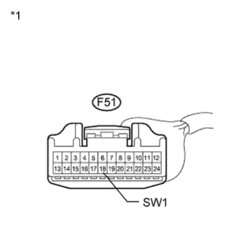
Text in Illustration *1 Front view of wire harness connector
(to Air Conditioning Amplifier Assembly)
Reconnect the front wiper deicer switch.
-
Disconnect the air conditioning amplifier assembly connector.
-
Turn the power switch on (IG).
-
Measure the voltage according to the value(s) in the table below.
Standard Voltage Tester Connection Condition Specified Condition F51-18 (SW1) - Body ground Front wiper deicer switch on 11 to 14 V F51-18 (SW1) - Body ground Front wiper deicer switch off Below 1 V
NG
CHECK HARNESS AND CONNECTOR (AIR CONDITIONING AMPLIFIER ASSEMBLY POWER SOURCE) Click here
OK 
REPLACE AIR CONDITIONING AMPLIFIER ASSEMBLY Click here
-
-
CHECK HARNESS AND CONNECTOR (AIR CONDITIONING AMPLIFIER ASSEMBLY POWER SOURCE)
-
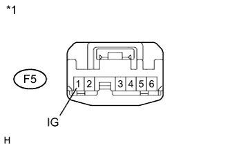
Text in Illustration *1 Front view of wire harness connector
(to Front Wiper Deicer Switch)
Disconnect the front wiper deicer switch connector.
-
Measure the voltage according to the value(s) in the table below.
Standard Voltage Tester Connection Condition Specified Condition F5-1 (IG) - Body ground Power switch on (IG) 11 to 14 V
NG
REPAIR OR REPLACE HARNESS OR CONNECTOR (FRONT WIPER DEICER SWITCH POWER SOURCE)
OK
REPAIR OR REPLACE HARNESS OR CONNECTOR (FRONT WIPER DEICER SWITCH - AIR CONDITIONING AMPLIFIER ASSEMBLY)
-
-
CHECK FRONT WIPER DEICER RELAY
-
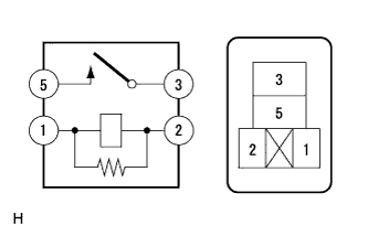
Remove the deicer relay from the engine room relay block.
-
Measure the resistance according to the value(s) in the table below.
Standard Resistance Tester Connection Condition Specified Condition Engine room relay block DEICER relay terminal 3 - 5 Battery voltage applied between terminals 1 and 2 Below 1 Ω Engine room relay block DEICER relay terminal 3 - 5 Battery voltage not applied between terminals 1 and 2 10 kΩ or higher
NG
REPLACE FRONT WIPER DEICER RELAY
OK
-
-
CHECK HARNESS AND CONNECTOR (DEICER RELAY TERMINAL - BODY GROUND)
-
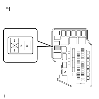
Text in Illustration *1 Front view of wire harness connector
(to Engine Room Block Assembly)
Measure the voltage according to the value(s) in the table below.
Standard Voltage Tester Connection Switch Condition Specified Condition Engine room relay block DEICER relay terminal 1 - Body ground Power switch off Below 1 V Engine room relay block DEICER relay terminal 1 - Body ground Power switch on (IG) 11 to 14 V
NG
REPAIR OR REPLACE HARNESS OR CONNECTOR
OK
-
-
CHECK HARNESS AND CONNECTOR (DEICER RELAY TERMINAL - AIR CONDITIONING AMPLIFIER ASSEMBLY)
-
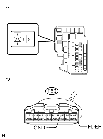
Text in Illustration *1 Front view of wire harness connector
(to Engine Room Block Assembly)
*2 Front view of wire harness connector
(to Air Conditioning Amplifier Assembly)
Disconnect the F50 air conditioning amplifier assembly connector.
-
Measure the resistance according to the value(s) in the table below.
Standard Resistance Tester Connection Condition Specified Condition Engine room relay block DEICER relay terminal 2 - F50-40 (FDEF) Always Below 1 Ω Engine room relay block DEICER relay terminal 2 - Body ground Always 10 kΩ or higher F50-14 (GND) - Body ground Always Below 1 Ω
NG
REPAIR OR REPLACE HARNESS OR CONNECTOR
OK
-
-
CHECK AIR CONDITIONING AMPLIFIER ASSEMBLY
-
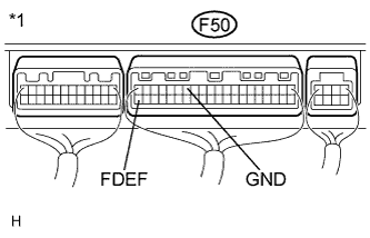
Text in Illustration *1 Front view of wire harness connector
(to Air Conditioning Amplifier Assembly)
Reconnect the DEICER relay.
-
Reconnect the F50 connector to the air conditioning amplifier.
-
Turn the power switch on (IG).
-
Measure the voltage according to the value(s) in the table below.
Standard Voltage Tester Connection Condition Specified Condition F50-40 (FDEF) - F50-14 (GND) Deicer switch on Below 1 V F50-40 (FDEF) - F50-14 (GND) Deicer switch off 11 to 14 V
NG
REPLACE AIR CONDITIONING AMPLIFIER ASSEMBLY Click here
OK
-
-
CHECK HARNESS AND CONNECTOR (DEICER RELAY TERMINAL - BODY GROUND)
-

Text in Illustration *1 Front view of wire harness connector
(to Engine Room Block Assembly)
Remove the DEICER relay from the engine room relay block.
-
Measure the voltage according to the value(s) in the table below.
Standard Voltage Tester Connection Condition Specified Condition Engine room relay block DEICER relay terminal 5 - Body ground Always 11 to 14 V
NG
REPAIR OR REPLACE HARNESS OR CONNECTOR
OK
-
-
CHECK HARNESS AND CONNECTOR (DEICER RELAY TERMINAL - WINDSHIELD GLASS (WINDSHIELD DEICER)
-
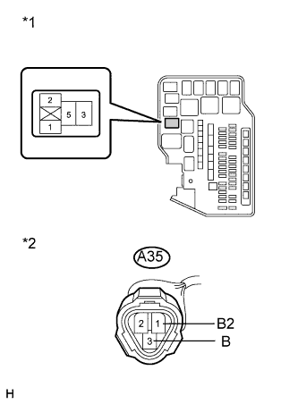
Text in Illustration *1 Front view of wire harness connector
(to Engine Room Block Assembly)
*2 Front view of wire harness connector
(to Windshield Glass (Windshield Deicer Wire))
Remove the DEICER relay from the engine room relay block.
-
Disconnect the A35 windshield glass windshield deicer wire connector.
-
Measure the resistance according to the value(s) in the table below.
Standard Resistance Tester Connection Condition Specified Condition Engine room relay block DEICER relay terminal 3 - A35-1 (B2) Always Below 1 Ω Engine room relay block DEICER relay terminal 3 - A35-3 (B) Always Below 1 Ω A35-1 - Body ground Always 10 kΩ or higher A35-3 - Body ground Always 10 kΩ or higher
NG
REPAIR OR REPLACE HARNESS OR CONNECTOR
OK
-
-
CHECK HARNESS AND CONNECTOR (WINDSHIELD GLASS (WINDSHIELD DEICER WIRE) - BODY GROUND)
-
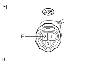
Text in Illustration *1 Front view of wire harness connector
(to Windshield Glass)
Measure the resistance according to the value(s) in the table below.
Standard Resistance Tester Connection Condition Specified Condition A35-2 (E) - Body ground Always Below 1 Ω
NG
REPAIR OR REPLACE HARNESS OR CONNECTOR
OK
REPLACE WINDSHIELD GLASS (WINDSHIELD DEICER WIRE) Click here
-