POWER WINDOW CONTROL SYSTEM Front Passenger Side Power Window Auto Up / Down Function does not Operate with Front Passenger Side Power Window Switch
DESCRIPTION
If the manual up and down function can be performed but the auto up and down function cannot, the fail-safe mode may be functioning.
If the power window initialization Click here has not been performed, the auto up and down function will not operate.
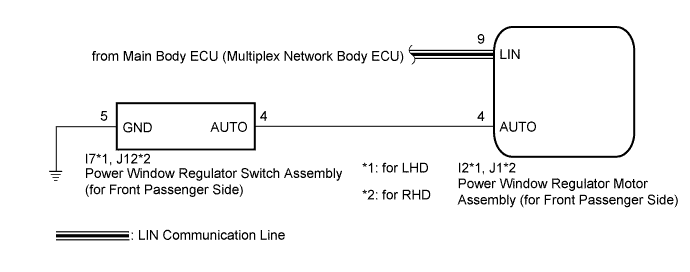
WIRING DIAGRAM
INSPECTION PROCEDURE
Note
-
The power window control system uses a multiplex communication system (LIN communication system). Inspect the communication function by following How to Proceed with Troubleshooting Click here. Troubleshoot the power window control system after confirming that the communication system is functioning properly.
-
When the power window regulator motor assembly (for front passenger side) is reinstalled or replaced, the power window control system must be initialized.
-
After a door glass or a door glass run has been replaced, the jam protection function may operate unexpectedly when the auto up function is used. In such cases, the auto up function can be reinitialized by repeating the following operations at least 5 times:
-
Close the power window by fully pulling up the power window regulator switch assembly (for front passenger side) and holding it at the auto up position.
-
Open the power window by fully pushing down the power window regulator switch assembly (for front passenger side).
-
When the ECU determines that the power window regulator motor assembly (for front passenger side) has a malfunction, DTC B2311 is set.
PROCEDURE
-
READ VALUE USING INTELLIGENT TESTER (P-Door Motor)
-
Connect the intelligent tester to the DLC3.
-
Turn the power switch on (IG).
-
Turn the intelligent tester on.
-
Enter the following menus: Body / P-Door Motor / Data List.
-
Read the Data List according to the display on the intelligent tester.
P-Door Motor (Power Window Regulator Motor Assembly (for Front Passenger Side)) Tester Display Measurement Item/Range Normal Condition Diagnostic Note P Door P/W Auto SW Front passenger side power window auto switch signal / ON or OFF ON: Front passenger door power window auto switch operated
OFF: Front passenger door power window auto switch not operated
- OK On the intelligent tester screen, ON or OFF is displayed accordingly.
NG 
INSPECT POWER WINDOW REGULATOR SWITCH ASSEMBLY (for Front Passenger Side) Click here
OK 
-
-
PERFORM INITIALIZATION (for Front Passenger Side)
-
Initialize the power window regulator motor assembly (for front passenger side) Click here.
NEXT
-
-
CHECK POWER WINDOW CONTROL SYSTEM (AUTO UP/DOWN FUNCTION)
-
Check that the front passenger side door power window moves when the auto up and down function of the power window regulator switch assembly (for front passenger side) is operated Click here.
OK Front passenger side auto up and down function is normal.
NG 
REPLACE POWER WINDOW REGULATOR MOTOR ASSEMBLY (for Front Passenger Side) Click here
OK 
END (PROBLEM DUE TO INITIALIZATION FAILURE)
-
-
INSPECT POWER WINDOW REGULATOR SWITCH ASSEMBLY (for Front Passenger Side)
-
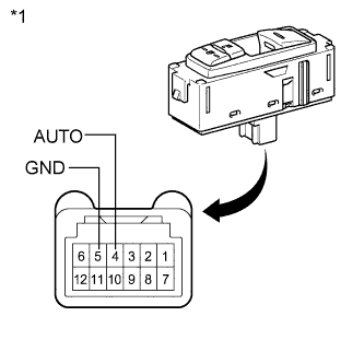
Text in Illustration *1 Component without harness connected
(Power Window Regulator Switch Assembly (for Front Passenger Side))
Remove the power window regulator switch assembly (for front passenger side) Click here.
-
Measure the resistance according to the value(s) in the table below.
Standard Resistance Tester Connection Switch Condition Specified Condition 4 (AUTO) - 5 (GND) Auto up or auto down position Below 1 Ω
NG
REPLACE POWER WINDOW REGULATOR SWITCH ASSEMBLY (for Front Passenger Side) Click here
OK
-
-
CHECK HARNESS AND CONNECTOR (POWER WINDOW SWITCH - REGULATOR MOTOR)
-
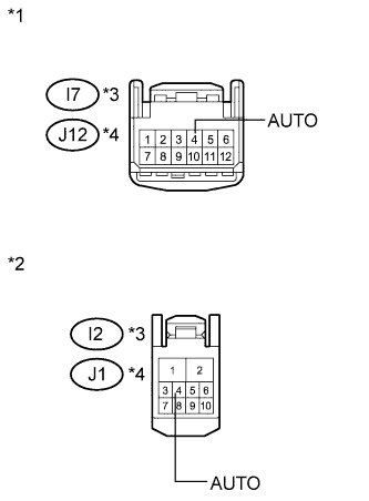
Text in Illustration *1 Front view of wire harness connector
(to Power Window Regulator Switch Assembly (for Front Passenger Side))
*2 Front view of wire harness connector
(to Power Window Regulator Motor Assembly (for Front Passenger Side))
*3 for LHD *4 for RHD Disconnect the power window regulator motor assembly (for front passenger side) connector.
-
Measure the resistance according to the value(s) in the table below.
Standard Resistance for LHD Tester Connection Condition Specified Condition I7-4 (AUTO) - I2-4 (AUTO) Always Below 1 Ω I7-4 (AUTO) - Body ground Always 10 kΩ or higher for RHD Tester Connection Condition Specified Condition J12-4 (AUTO) - J1-4 (AUTO) Always Below 1 Ω J12-4 (AUTO) - Body ground Always 10 kΩ or higher
NG
REPAIR OR REPLACE HARNESS OR CONNECTOR
OK
REPLACE POWER WINDOW REGULATOR MOTOR ASSEMBLY (for Front Passenger Side) Click here
-