ROOF HEADLINING INSTALLATION

-
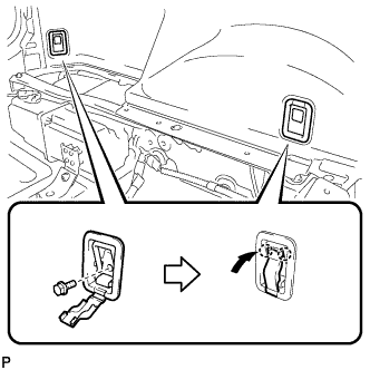
INSTALL REAR DOOR OPENING TRIM WEATHERSTRIP LH
-
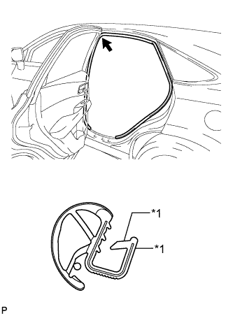
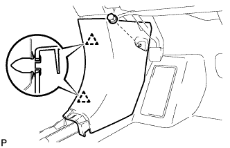
Text in Illustration *1 Alignment mark (Brown) Align the alignment mark (Brown) on the weatherstrip with the protruding portion on the body indicated by the arrow in the illustration, and install the rear door opening trim weatherstrip LH.
Note
After installation, check that the corners fit correctly.
-
-
INSTALL REAR DOOR OPENING TRIM WEATHERSTRIP RH
-
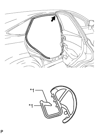
Text in Illustration *1 Alignment mark (Pink) Align the alignment mark (Pink) on the weatherstrip with the protruding portion on the body indicated by the arrow in the illustration, and install the rear door opening trim weatherstrip RH.
Note
After installation, check that the corners fit correctly.
-
-
INSTALL FRONT DOOR OPENING TRIM WEATHERSTRIP LH
-
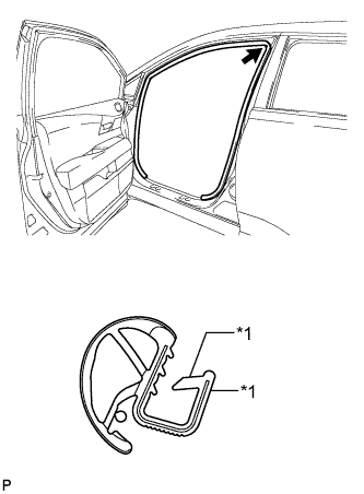
Text in Illustration *1 Alignment mark (Light Blue) Align the alignment mark (Light Blue) on the weatherstrip with the protruding portion on the body indicated by the arrow in the illustration, and install the front door opening trim weatherstrip LH.
Note
After installation, check that the corners fit correctly.
-
-
INSTALL FRONT DOOR OPENING TRIM WEATHERSTRIP RH
-
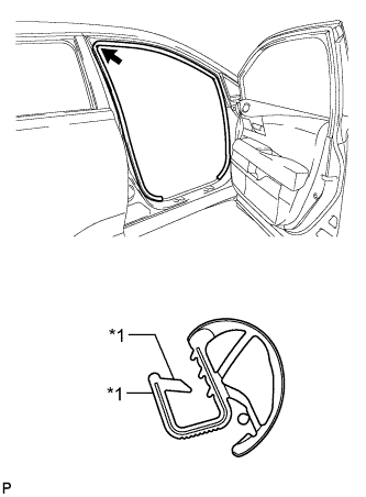
Text in Illustration *1 Alignment mark (Green) Align the alignment mark (Green) on the weatherstrip with the protruding portion on the body indicated by the arrow in the illustration, and install the front door opening trim weatherstrip RH.
Note
After installation, check that the corners fit correctly.
-
-
INSTALL ROOF HEADLINING ASSEMBLY (for Standard Roof)
-
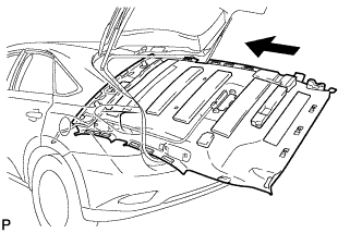
Pull the roof headlining assembly into the vehicle through the back door.
Note
Do not damage the roof headlining assembly or body interior.
-
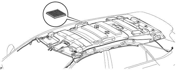
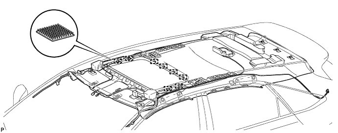
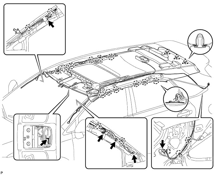
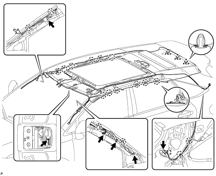
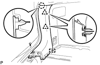
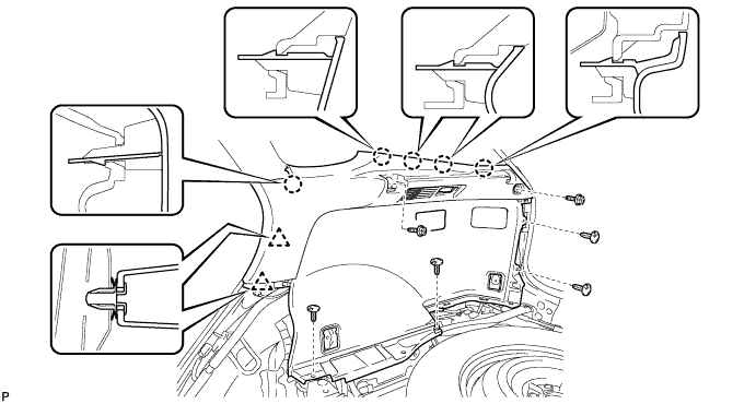
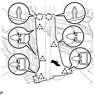
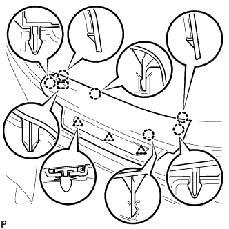
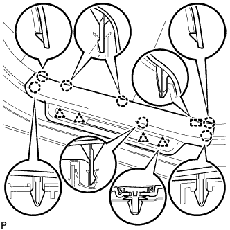
Engage the 2 fasteners.
-
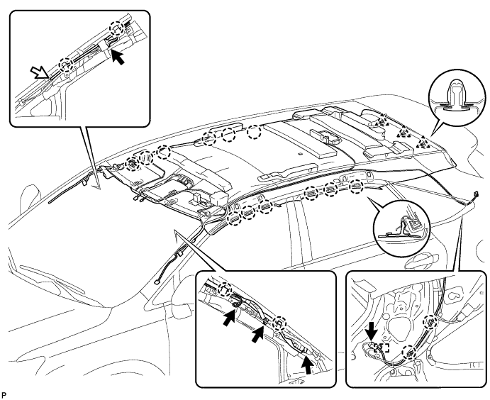
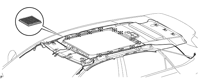
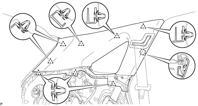
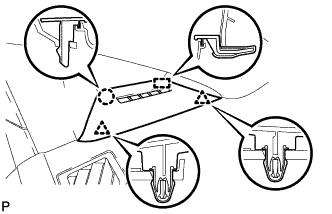
Engage the 12 claws and 3 clips.
-
Connect the No. 4 antenna cord sub-assembly connector and engage the 2 claws and clamp to the rear pillar LH.
-
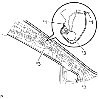
Connect the No. 2 antenna cord sub-assembly connector and washer hose, and engage the 2 claws to the front pillar RH.
-
Connect the No. 4 antenna cord sub-assembly connector and No. 1 roof wire connectors, and engage the 2 claws to the front pillar LH.
Note
After installation, make sure that the back door weatherstrip does not interfere with the roof headlining assembly.
-
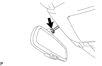
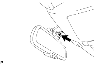
Connect the No. 1 roof wire connector to the inner rear view mirror.
-
w/ Rain Sensor:
-
Connect the No. 1 roof wire connector to the rain sensor.
-
-
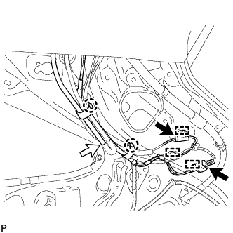
Connect the No. 2 antenna cord sub-assembly connectors and washer hose, and engage the 2 claws and 3 clamps to the rear pillar RH.
-
-
INSTALL ROOF HEADLINING ASSEMBLY (for Sliding roof)
-
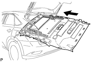
Pull the roof headlining assembly into the vehicle through the back door.
Note
Do not damage the roof headlining assembly or body interior.
-
Engage the 8 fasteners.
-
Engage the 12 claws and 3 clips.
-
Connect the No. 4 antenna cord sub-assembly connector and engage the 2 claws and clamp to the rear pillar LH.
-
Connect the No. 1 roof wire connector to the sliding roof drive gear assembly.
-
Connect the No. 2 antenna cord sub-assembly connector and washer hose, and engage the 2 claws to the front pillar RH.
-
Connect the No. 4 antenna cord sub-assembly connector and No. 1 roof wire connectors, and engage the 2 claws to the front pillar LH.
Note
After installation, make sure that the back door weatherstrip does not interfere with the roof headlining assembly.
-
Connect the No. 1 roof wire connector to the inner rear view mirror.
-
w/ Rain Sensor:
-
Connect the No. 1 roof wire connector to the rain sensor.
-
-
Connect the No. 2 antenna cord sub-assembly connectors and washer hose, and engage the 2 claws and 3 clamps to the rear pillar RH.
-
-
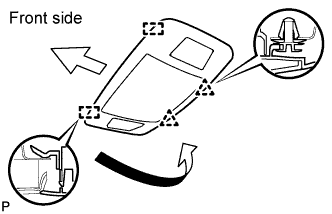
INSTALL ROOF HEADLINING ASSEMBLY (for Glass Roof)
-
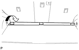
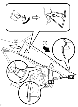
Open the sunshade trim sub-assembly as shown in the illustration.
Note
If the sunshade trim sub-assembly is closed, the roof headlining cannot be installed.
-
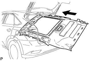
Pull the roof headlining assembly into the vehicle through the back door.
Note
Do not damage the roof headlining assembly or body interior.
-
Engage the 12 fasteners.
-
Engage the 12 claws and 3 clips.
-
Connect the No. 4 antenna cord sub-assembly connector and engage the 2 claws and clamp to the rear pillar LH.
-
Connect the No. 1 roof wire connector to the sliding roof drive gear assembly.
-
Connect the No. 2 antenna cord sub-assembly connector and washer hose, and engage the 2 claws to the front pillar RH.
-
Connect the No. 4 antenna cord sub-assembly connector and No. 1 roof wire connectors, and engage the 2 claws to the front pillar LH.
Note
After installation, make sure that the back door weatherstrip does not interfere with the roof headlining assembly.
-
Connect the No. 1 roof wire connector to the inner rear view mirror.
-
w/ Rain Sensor:
-
Connect the No. 1 roof wire connector to the rain sensor.
-
-
Connect the No. 2 antenna cord sub-assembly connectors and washer hose, and engage the 2 claws and 3 clamps to the rear pillar RH.
-
-
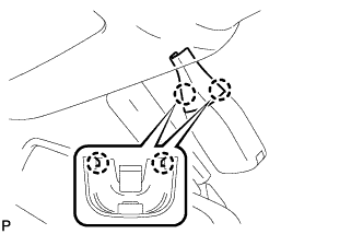
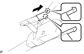
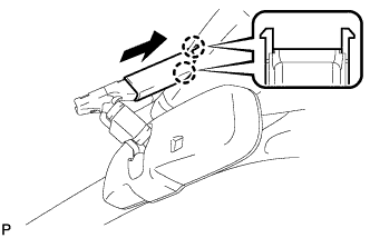
INSTALL VISOR HOLDER (for LH Side)
-
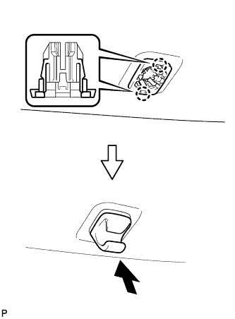
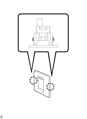
Engage the 2 claws.
-
Push in the visor holder as shown in the illustration.
-
-
INSTALL VISOR HOLDER (for RH Side)
Tech Tips
Use the same procedure for the RH side and the LH side.
-
INSTALL VISOR ASSEMBLY LH
-
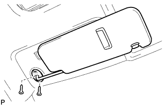
Install the visor assembly LH with the 2 screws.
-
-
INSTALL VISOR BRACKET COVER (for LH Side)
-
Engage the 4 claws and install the visor bracket cover.
-
-
INSTALL VISOR ASSEMBLY RH
Tech Tips
Use the same procedure for the RH side and the LH side.
-
INSTALL VISOR BRACKET COVER (for RH Side)
Tech Tips
Use the same procedure for the RH side and the LH side.
-
INSTALL ASSIST GRIP SUB-ASSEMBLY
-
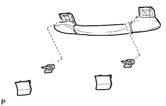
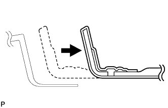
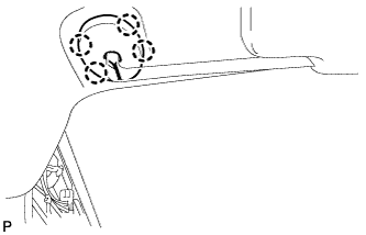
Put an assist grip sub-assembly together as shown in the illustration.
-
Install the assist grip sub-assembly.
Tech Tips
Use the same procedure for the other 3 assist grips.
-
-
INSTALL COAT HOOK
-
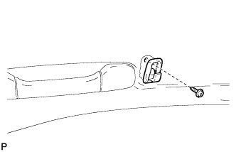
Install the coat hook with the screw.
Tech Tips
Use the same procedure for the RH side and the LH side.
-
-
INSTALL RAIN SENSOR COVER (w/ Rain Sensor)
-
Engage the 2 claws to install the rain sensor cover.
-
-
INSTALL INNER REAR VIEW MIRROR STAY HOLDER COVER (w/ EC Mirror)
-
w/o Rear View Monitor System:
-
Engage the 6 claws and install the inner rear view mirror stay holder cover.
-
Engage the 2 claws and install the inner rear view mirror stay holder cover as shown in the illustration.
-
-
w/ Rear View Monitor System:
-
Engage the 2 claws and install the inner rear view mirror stay holder cover.
-
Engage the 2 claws and install the inner rear view mirror stay holder cover as shown in the illustration.
-
-
-
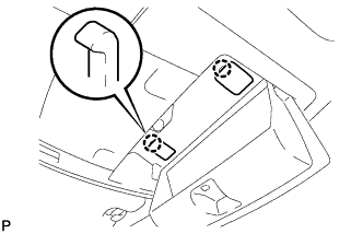
INSTALL SPOT LIGHT ASSEMBLY
-
Connect the connector.
-
Insert the 2 guides.
-
Engage the 2 clips to install the spot light assembly as shown in the illustration.
-
-
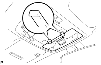
INSTALL MAP LIGHT ASSEMBLY
-
Connect each connector.
-
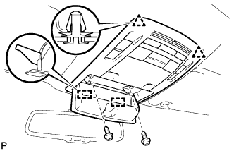
Engage the 2 guides and 2 clips.
-
Install the map light assembly with the 2 screws.
-
Engage the 2 claws and connect the 2 caps.
-
w/ Holder:
-
Close the holder.
-
-
w/o Holder:
-
Engage the 2 claws to connect the cover.
-
-
-
INSTALL ROOF SIDE INNER GARNISH ASSEMBLY LH
-
Pass the floor anchor of the rear seat outer seat belt assembly LH through the roof side inner garnish assembly LH.
-
Engage the claw and 8 clips to install the roof side inner garnish assembly LH.
-
-
CONNECT REAR SEAT OUTER BELT ASSEMBLY LH
-
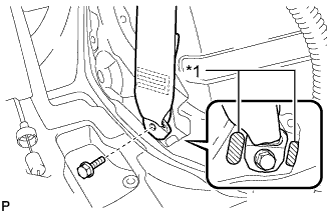
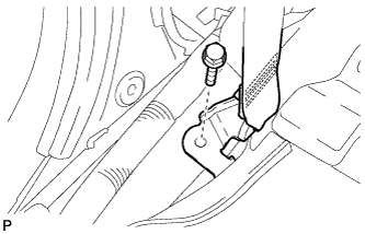
Text in Illustration *1 Protruding Part Connect the floor anchor end of the rear seat belt assembly and install the bolt.
- Torque:
- 42 N*m { 428 kgf*cm, 31 ft.*lbf }
Note
Do not allow the anchor part of the rear seat outer belt assembly to overlap the protruding part of the floor panel.
-
-
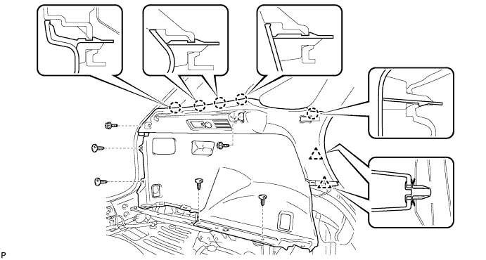
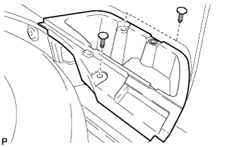
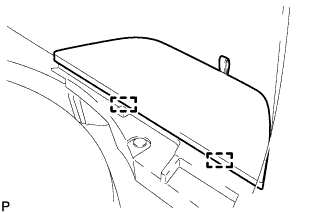
INSTALL DECK TRIM SIDE PANEL ASSEMBLY LH
-
Connect each connector.
-
Engage the 2 clips and the 5 claws.
-
Install the deck trim side panel assembly LH with the 2 bolts and 4 clips.
-
-
INSTALL RECLINING REMOTE CONTROL BEZEL LH
-
Engage the 4 claws and install the reclining remote control bezel LH.
-
-
INSTALL NO. 1 LUGGAGE COMPARTMENT TRIM HOOK (for LH Side)
-
Install the No. 1 luggage compartment trim hook as shown in the illustration.
-
-
INSTALL ROPE HOOK ASSEMBLY (for LH Side)
-
Install the 2 rope hook assemblies with the 2 bolts.
-
Engage the 2 claws.
-
-
INSTALL REAR SEAT SIDE COVER LH
-
Engage the 2 claws and 3 clips.
-
Install the rear seat side cover LH with the 2 clips.
-
-
INSTALL REAR SEAT ASSEMBLY LH
-
Install the rear seat assembly LH Click here.
-
-
INSTALL REAR FLOOR FINISH SIDE PLATE LH
-
Engage the guide.
-
Engage the claw and 2 clips.
-
Install the rear floor finish side plate LH with the clip.
-
-
INSTALL ROOF SIDE INNER GARNISH ASSEMBLY RH
Tech Tips
Use the same procedure for the RH side and the LH side.
-
CONNECT REAR SEAT OUTER BELT ASSEMBLY RH
Tech Tips
Use the same procedure for the RH side and the LH side.
-
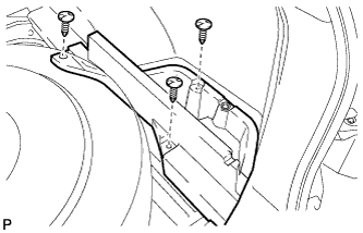
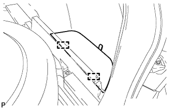
INSTALL DECK TRIM SIDE PANEL ASSEMBLY RH
-
Connect the connector.
-
Engage the 2 clips and the 5 claws.
-
Install the deck trim side panel assembly RH with the 2 bolts and 5 clips.
-
-
INSTALL HEIGHT CONTROL SWITCH (w/ Air Suspension)
-
Connect the connector.
-
Engage the 2 claws to install the height control switch to the deck trim side panel assembly RH.
-
-
INSTALL RECLINING REMOTE CONTROL BEZEL RH
Tech Tips
Use the same procedure for the RH side and the LH side.
-
INSTALL NO. 1 LUGGAGE COMPARTMENT TRIM HOOK (for RH Side)
-
Install the No. 1 luggage compartment trim hook as shown in the illustration.
-
-
INSTALL ROPE HOOK ASSEMBLY (for RH Side)
Tech Tips
Use the same procedure for the RH side and the LH side.
-
INSTALL REAR SEAT SIDE COVER RH
Tech Tips
Use the same procedure for the RH side and the LH side.
-
INSTALL REAR SEAT ASSEMBLY RH
-
Install the rear seat assembly RH Click here.
-
-
INSTALL REAR FLOOR FINISH SIDE PLATE RH
Tech Tips
Use the same procedure for the RH side and the LH side.
-
INSTALL REAR FLOOR FINISH PLATE
-
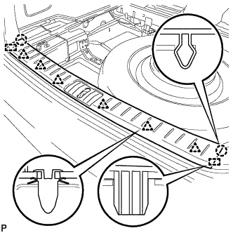
Engage the 6 clips, 2 claws and 2 guides, and install the rear floor finish plate.
-
-
INSTALL FRONT DECK FLOOR BOX
-
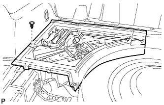
Install the front deck floor box with the clip.
-
-
INSTALL DECK SIDE TRIM BOX LH (for Compact Spare Tire)
-
Install the deck side trim box LH with the 2 clips.
-
-
INSTALL DECK SIDE TRIM BOX LH (for Full Size Spare Tire)
-
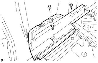
Install the deck side trim box LH with the 3 clips.
-
-
INSTALL DECK SIDE TRIM BOX RH (for Compact Spare Tire)
-
Install the deck side trim box RH with the 2 clips.
-
-
INSTALL DECK SIDE TRIM BOX RH (for Full Size Spare Tire)
-
Install the deck side trim box RH with the 3 clips.
-
-
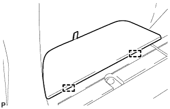
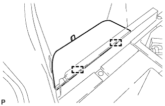
INSTALL TONNEAU COVER ASSEMBLY
-
Install the tonneau cover assembly.
-
-
INSTALL NO. 3 REAR FLOOR BOARD (for Compact Spare Tire)
-
Engage the 2 guides and install the No. 3 rear floor board.
-
-
INSTALL NO. 3 REAR FLOOR BOARD (for Full Size Spare Tire)
-
Engage the 2 guides and install the No. 3 rear floor board.
-
-
INSTALL NO. 4 REAR FLOOR BOARD (for Compact Spare Tire)
-
Engage the 2 guides and install the No. 4 rear floor board.
-
-
INSTALL NO. 4 REAR FLOOR BOARD (for Full Size Spare Tire)
-
Engage the 2 guides and install the No. 4 rear floor board.
-
-
INSTALL SPARE WHEEL COVER ASSEMBLY (for Compact Spare Tire)
-
Install the spare wheel cover assembly.
-
-
INSTALL DECK BOARD SUB-ASSEMBLY
-
for Compact Spare Tire:
-
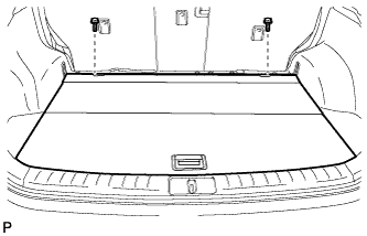
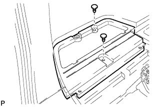
Install the deck board sub-assembly with the 2 bolts.
-
-
for Full Size Spare Tire:
-
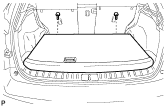
Install the deck board sub-assembly with the 2 bolts.
-
-
Engage the 3 fasteners as shown in the illustration.
-
-
INSTALL CENTER PILLAR GARNISH LH
-
Pass the floor anchor of the front seat outer seat belt assembly LH through the center pillar garnish LH.
-
Engage the clip to install the center pillar garnish LH with the 2 screws.
-
-
CONNECT FRONT SEAT OUTER BELT ASSEMBLY LH
-
Install the floor end of the front seat outer belt assembly with the bolt.
- Torque:
- 42 N*m { 428 kgf*cm, 31 ft.*lbf }
-
Check if the ELR locks.
Note
The check should be performed with the outer belt assembly installed.
-
With the belt assembly installed, check that the belt locks when it is pulled out quickly.
-
-
-
INSTALL LOWER CENTER PILLAR GARNISH LH
-
Engage the 2 claws and the 5 clips to install the lower center pillar garnish LH.
-
-
INSTALL REAR DOOR SCUFF PLATE LH
-
Engage the 3 clips, guide and 6 claws, and install the rear door scuff plate LH.
-
-
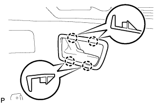
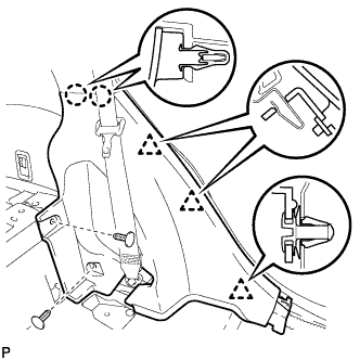
INSTALL FRONT PILLAR GARNISH LH
-
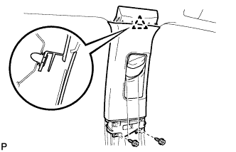
Text in Illustration *1 Adhesive Tape *2 Protective Cover *3 Curtain Shield Airbag Assembly Remove the protective cover.
-
Make sure that the front pillar garnish clip is not damaged.
Note
-
If there is any damage, replace the garnish clip with a new one.
-
When a garnish clip is being replaced, make sure to install it in the direction shown in the illustration.
-
-
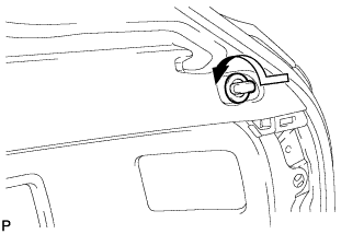
Engage the 2 guides.
-
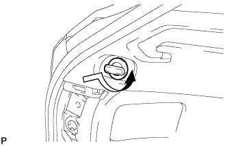
Turn the end of the front pillar garnish clip 90° with needle-nosed pliers and install it to the front pillar garnish LH.
Tech Tips
Tape the tips of the needle-nosed pliers before use.
-
Engage the 2 clips to install the front pillar garnish LH.
-
-
INSTALL INSTRUMENT SIDE PANEL LH
-
Engage the guide.
-
Engage the 2 clips.
-
Engage the claw to install the instrument side panel LH.
-
-
INSTALL COWL SIDE TRIM SUB-ASSEMBLY LH
-
Engage the 2 clips to install the cowl side trim sub-assembly LH.
-
Install the clip.
-
-
INSTALL FRONT DOOR SCUFF PLATE LH
-
w/ Illumination:
-
Connect the connector.
-
-
Engage the 4 clips, guide and 7 claws, and install the front door scuff plate LH.
-
-
INSTALL CENTER PILLAR GARNISH RH
Tech Tips
Use the same procedure for the RH side and the LH side.
-
CONNECT FRONT SEAT OUTER BELT ASSEMBLY RH
Tech Tips
Use the same procedure for the RH side and the LH side.
-
INSTALL LOWER CENTER PILLAR GARNISH RH
Tech Tips
Use the same procedure for the RH side and the LH side.
-
INSTALL REAR DOOR SCUFF PLATE RH
Tech Tips
Use the same procedure for the RH side and the LH side.
-
INSTALL FRONT PILLAR GARNISH RH
Tech Tips
Use the same procedure for the RH side and the LH side.
-
INSTALL INSTRUMENT SIDE PANEL RH
Tech Tips
Use the same procedure for the RH side and the LH side.
-
INSTALL COWL SIDE TRIM SUB-ASSEMBLY RH
Tech Tips
Use the same procedure for the RH side and the LH side.
-
INSTALL FRONT DOOR SCUFF PLATE RH
Tech Tips
Use the same procedure for the RH side and the LH side.
-
CONNECT CABLE TO NEGATIVE BATTERY TERMINAL
Note
When disconnecting the cable, some systems need to be initialized after the cable is reconnected Click here.
-
INSTALL REAR DECK FLOOR BOX
-

Install the rear deck floor box with the 3 clips.
-
-
INSPECT SRS WARNING LIGHT
-
Inspect the SRS warning light Click here.
-
-
INSPECT SUSPENSION CONTROL SYSTEM (w/ Air Suspension)
-
Inspect the suspension control system Click here.
-