ROOF HEADLINING REASSEMBLY

-
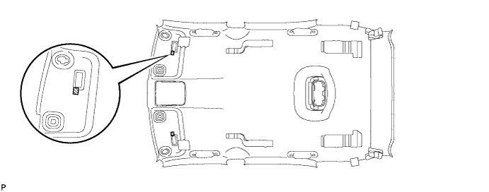
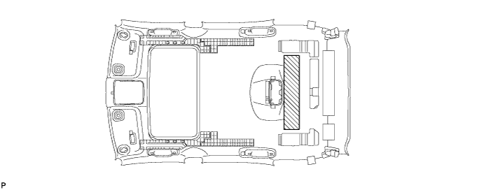
INSTALL NO. 1 ROOF PANEL PAD
-
Align the markings on the roof headlining assembly with the No. 1 roof panel pad and install the pad using hot-melt glue or double-sided tape as shown in the illustration.
-
-
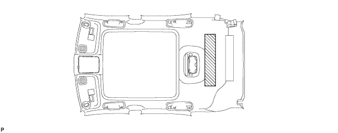
INSTALL NO. 3 ROOF PANEL PAD (w/o Power Back Door)
Tech Tips
Use the same procedure for the RH side and the LH side.
-
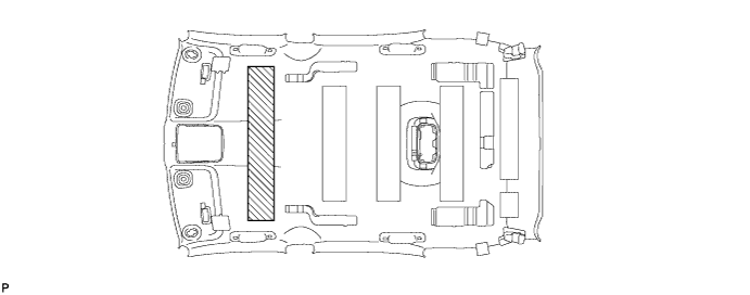
INSTALL REAR QUARTER TRIM SILENCER PAD RH
-
Align the markings on the roof headlining assembly with the rear quarter trim silencer pad RH and install the silencer pad using hot-melt glue or double-sided tape as shown in the illustration.
-
-
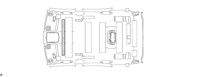
INSTALL REAR QUARTER TRIM SILENCER PAD LH (w/o Power Back Door)
Tech Tips
Use the same procedure for the RH side and the LH side.
-
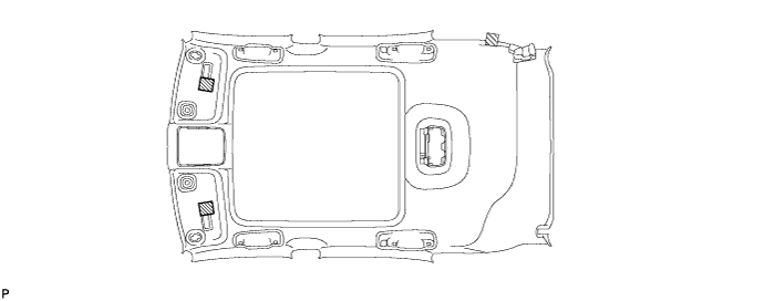
INSTALL ROOF HEADLINING FORMING PAD (except Glass Roof)
-
Align the markings on the roof headlining assembly with the roof headlining forming pad and install the forming pad using hot-melt glue or double-sided tape as shown in the illustration.
-
-
INSTALL ROOF HEADLINING FORMING PAD (for Glass Roof)
-
Align the markings on the roof headlining assembly with the roof headlining forming pad and install the forming pad using hot-melt glue or double-sided tape as shown in the illustration.
-
-
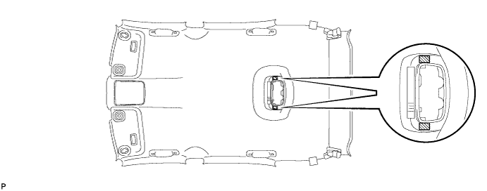
INSTALL CENTER ROOF HEADLINING PAD
-
Align the markings on the roof headlining assembly with the 2 center roof headlining pads and install the pads using hot-melt glue or double-sided tape as shown in the illustration.
-
-
INSTALL NO. 2 ROOF HEADLINING SET PLATE RH (for Sliding roof)
-
Align the markings on the roof headlining assembly with the No. 2 roof headlining set plate RH and install the plate using hot-melt glue or double-sided tape as shown in the illustration.
-
-
INSTALL NO. 2 ROOF HEADLINING SET PLATE LH (for Sliding roof)
Tech Tips
Use the same procedure for the RH side and the LH side.
-
INSTALL ROOF HEADLINING SET PLATE RH (for Sliding roof)
-
Align the markings on the roof headlining assembly with the roof headlining set plate RH and install the plate using hot-melt glue or double-sided tape as shown in the illustration.
-
-
INSTALL ROOF HEADLINING SET PLATE LH (for Sliding roof)
Tech Tips
Use the same procedure for the RH side and the LH side.
-
INSTALL ROOF HEADLINING PAD LH (except Glass Roof)
-
w/o Power Back Door:
-
Align the markings on the roof headlining assembly with the roof headlining pad LH and install the pad using hot-melt glue or double-sided tape as shown in the illustration.
-
-
w/ Power Back Door:
-
Align the markings on the roof headlining assembly with the roof headlining pad LH and install the pad using hot-melt glue or double-sided tape as shown in the illustration.
-
-
-
INSTALL ROOF HEADLINING PAD RH (except Glass Roof)
-
Align the markings on the roof headlining assembly with the roof headlining pad RH and install the pad using hot-melt glue or double-sided tape as shown in the illustration.
-
-
INSTALL REAR SIDE RAIL SPACER RH (for Standard Roof)
-
Align the markings on the roof headlining assembly with the rear side rail spacer RH and install the spacer using hot-melt glue or double-sided tape as shown in the illustration.
-
-
INSTALL REAR SIDE RAIL SPACER LH (for Standard Roof)
Tech Tips
Use the same procedure for the RH side and the LH side.
-
INSTALL FRONT SIDE RAIL SPACER RH (for Standard Roof)
-
Align the markings on the roof headlining assembly with the front side rail spacer RH and install the spacer using hot-melt glue or double-sided tape as shown in the illustration.
-
-
INSTALL FRONT SIDE RAIL SPACER LH (for Standard Roof)
Tech Tips
Use the same procedure for the RH side and the LH side.
-
INSTALL FRONT ROOF HEADLINING SIDE PAD (except Glass Roof)
-
Align the markings on the roof headlining assembly with the 2 front roof headlining side pads and install the pads using hot-melt glue or double-sided tape as shown in the illustration.
-
-
INSTALL FRONT ROOF HEADLINING SIDE PAD (for Glass Roof)
-
Align the markings on the roof headlining assembly with the 2 front roof headlining side pads and install the pads using hot-melt glue or double-sided tape as shown in the illustration.
-
-
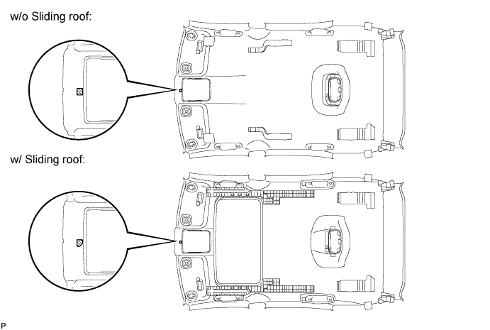
INSTALL ROOF HEADLINING PAD (except Glass Roof)
-
Align the markings on the roof headlining assembly with the roof headlining pad and install the pad using hot-melt glue or double-sided tape as shown in the illustration.
-
-
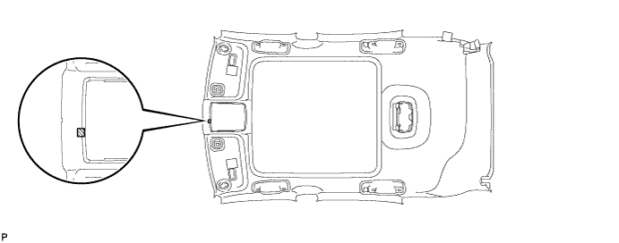
INSTALL ROOF HEADLINING PAD (for Glass Roof)
-
Align the markings on the roof headlining assembly with the roof headlining pad and install the pad using hot-melt glue or double-sided tape as shown in the illustration.
-
-
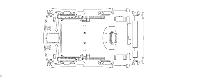
INSTALL ROOF HEADLINING SPACER (except Glass Roof)
-
Align the markings on the roof headlining assembly with the roof headlining spacer and install the spacer using hot-melt glue or double-sided tape as shown in the illustration.
-
-
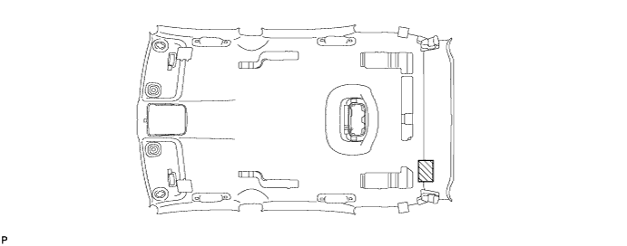
INSTALL ROOF SIDE RAIL SILENCER PAD LH (w/o Power Back Door)
-
Align the markings on the roof headlining assembly with the roof side rail silencer pad LH and install the silencer pad using hot-melt glue or double-sided tape as shown in the illustration.
-
-
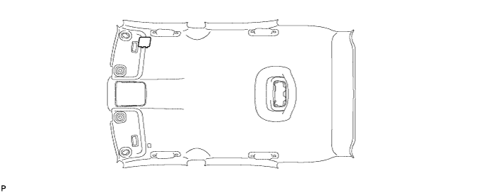
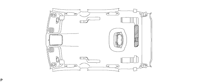
INSTALL NO. 3 ROOF SILENCER
-
Align the markings on the roof headlining assembly with the No. 3 roof silencer and install the silencer using hot-melt glue or double-sided tape as shown in the illustration.
-
-
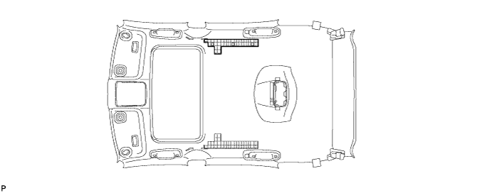
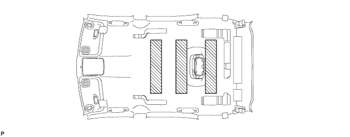
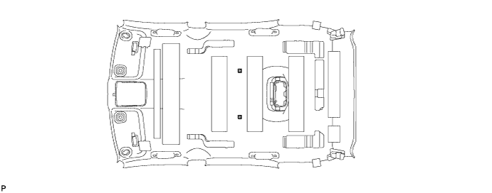
INSTALL NO. 2 ROOF SILENCER (for Standard Roof)
-
Align the markings on the roof headlining assembly with the 3 No. 2 roof silencers and install the silencers using hot-melt glue or double-sided tape as shown in the illustration.
-
-
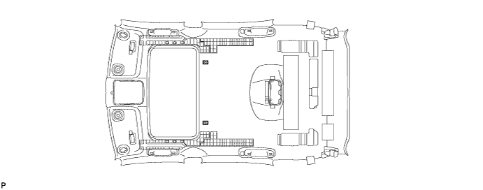
INSTALL NO. 2 ROOF SILENCER (for Sliding roof)
-
Align the markings on the roof headlining assembly with the No. 2 roof silencer and install the silencer using hot-melt glue or double-sided tape as shown in the illustration.
-
-
INSTALL NO. 2 ROOF SILENCER (for Glass Roof)
-
Align the markings on the roof headlining assembly with the No. 2 roof silencer and install the silencer using hot-melt glue or double-sided tape as shown in the illustration.
-
-
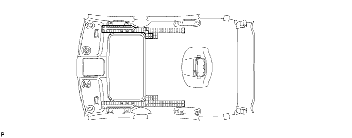
INSTALL NO. 1 ROOF SILENCER (for Standard Roof)
-
Align the markings on the roof headlining assembly with the No. 1 roof silencer and install the silencer using hot-melt glue or double-sided tape as shown in the illustration.
-
-
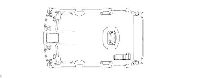
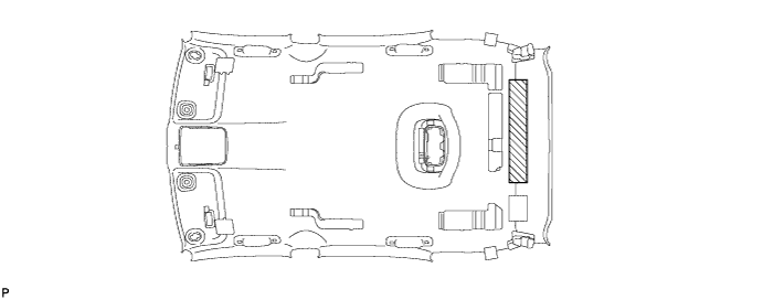
INSTALL CENTER ROOF SILENCER PAD (for Standard Roof)
-
Align the markings on the roof headlining assembly with the center roof silencer pad and install the silencer pad using hot-melt glue or double-sided tape as shown in the illustration.
-
-
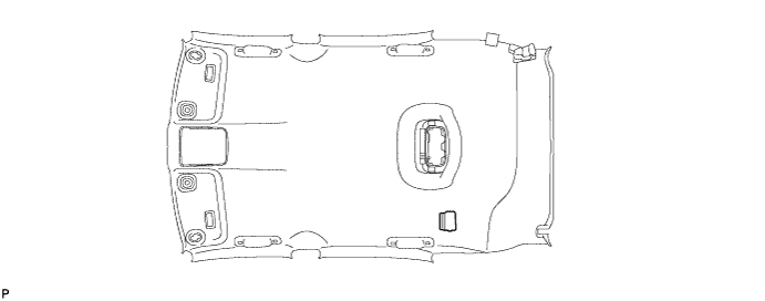
INSTALL SUNSHADE TRIM PROTECTOR (for Standard Roof)
-
Install 2 new sunshade trim protectors.
-
Remove the release paper from the 2 sunshade trim protectors.
Tech Tips
After removing the release paper, keep the exposed adhesive free from foreign matter.
-
Align the markings on the roof headlining assembly with the 2 sunshade trim protectors and install the 2 protectors as shown in the illustration.
-
-
-
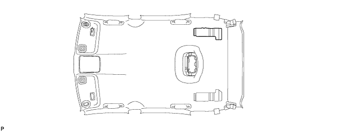
INSTALL NO. 2 HOOK FASTENER (for Sliding roof)
-
Align the markings on the roof headlining assembly with the 2 No. 2 hook fasteners and install the fastener using hot-melt glue as shown in the illustration.
-
-
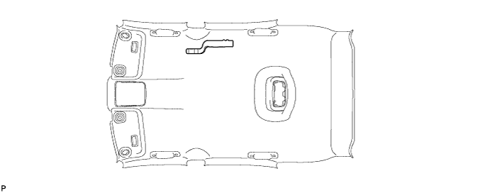
INSTALL NO. 1 HOOK FASTENER (for Sliding roof)
-
Align the markings on the roof headlining assembly with the 2 No. 1 hook fasteners and install the fastener using hot-melt glue as shown in the illustration.
-
-
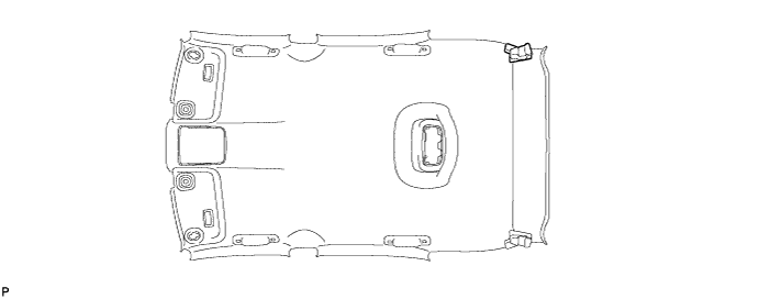
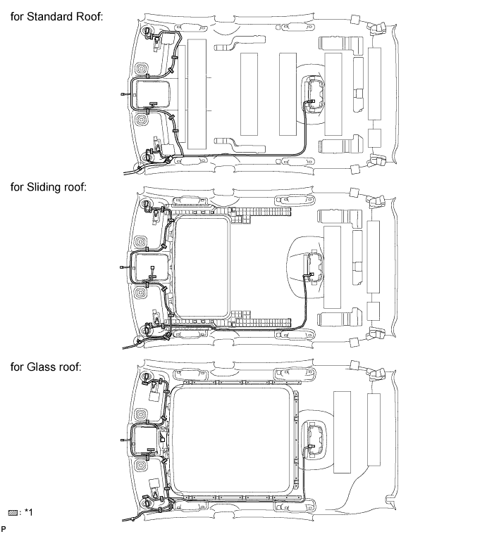
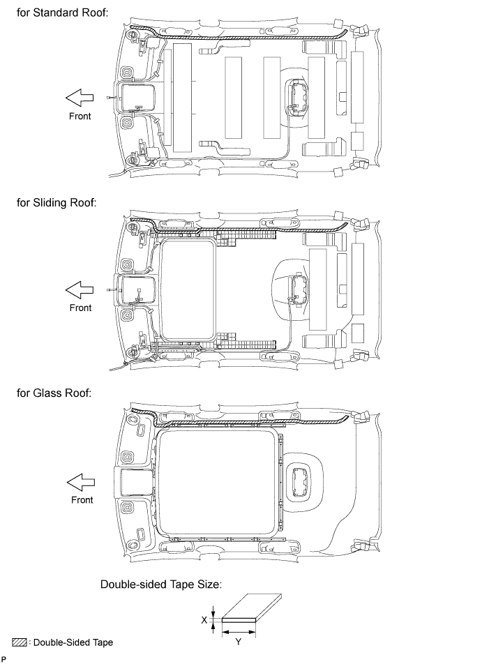
INSTALL NO. 1 ROOF WIRE
-
Apply new double-sided tape.
-
Remove the double-sided tape from the roof headlining assembly.
-
Peel off the appropriate amount of new double sided tape.
Area Dimension X 1.0 mm (0.0394 in.) Y 15.0 mm (0.591 in.) Note
Be careful not to touch the adhesive surface.
-
Apply the double sided tape to the roof headlining while aligning the tape with the markings on the roof headlining assembly.
-
Peel off the backing sheet from the double sided tape.
-
-
Install the No. 1 roof wire to the roof headlining assembly.
Tech Tips
-
For the left front corner <A> of the roof headlining assembly, align the marking tape (white) on the No. 1 roof wire with the protrusion of the roof headlining.
-
Align the markings on the roof headlining assembly with the joint box.
-
-
Turn the visor connectors clockwise approximately 90° to install the connectors to the roof headlining assembly.
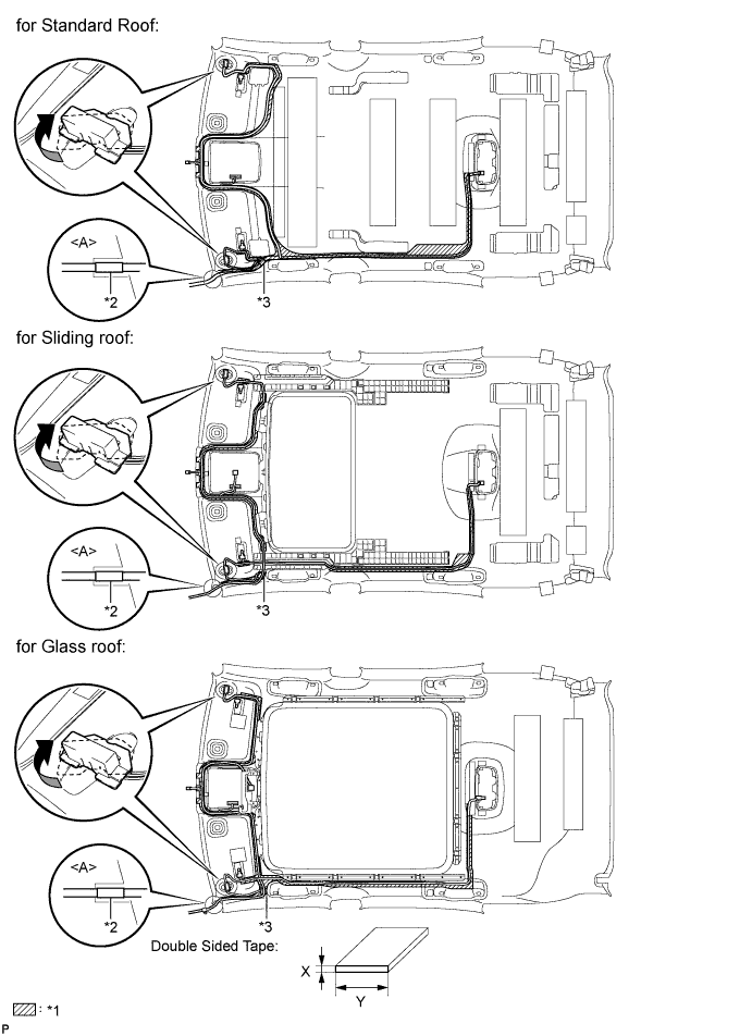
Text in Illustration *1 Double Sided Tape Area *2 Marking Tape *3 Joint Box - - -
Apply adhesive tape to the locations shown in the illustration.
Text in Illustration *1 Adhesive Tape Tech Tips
As shown in the illustration, line up and secure the reference tape of the wire harness to the tip of the roof headlining assembly.
-
-
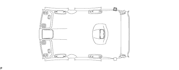
INSTALL REAR NO. 3 WASHER HOSE
Tech Tips
The double-sided tape is not available as supply parts. If the tape still has enough adhesion to secure the roof headlining and rear No. 3 washer hose, reuse the tape. If the roof headlining has been replaced with a new one, or if the tape and/or the double-sided tape is no longer sticky, apply new tape following the procedure below.
-
Apply new double-sided tape.
-
Remove the double-sided tape from the roof headlining assembly.
-
Peel off the appropriate amount of new double sided tape.
Area Dimension X 1.0 mm (0.0394 in.) Y 15.0 mm (0.591 in.) Note
Be careful not to touch the adhesive surface.
-
Apply the double-sided tape to the roof headlining while aligning the tape with the markings on the roof headlining assembly.
-
Peel off the backing sheet from the double sided tape.
-
-
Install the rear No. 3 washer hose to the roof headlining assembly from the front of the vehicle.
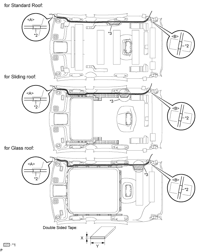
Text in Illustration *1 Double Sided Tape Area *2 Marking Tape *3 Adjustment Area - - Tech Tips
-
For the right front corner <A> of the roof headlining assembly, align the marking tape (green) on the rear No. 3 washer hose with the protrusion of the roof headlining.
-
For the right rear corner <B> of the roof headlining assembly, align the marking tape (green) on the rear No. 3 washer hose with the marking of the roof headlining.
-
If the entire length of the rear No. 3 washer hose does not fit, adjust the length by tucking in the hose at the area shown in the illustration.
-
-
-
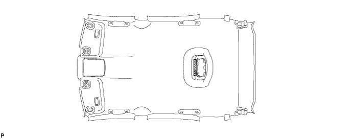
INSTALL NO. 5 ANTENNA CORD SUB-ASSEMBLY
Tech Tips
Double-sided tape and tape are not available as supply parts. If the tape still has enough adhesion to secure the roof headlining and antenna cord, reuse it. If the roof headlining has been replaced with a new one, or if the tape and/or the double-sided tape is no longer sticky, apply new tape following the procedure below.
If the double-sided tape cannot be reused:
-
Peel off the release paper from one side of new double-sided tape and apply the new double-sided tape to the position indicated in the illustration. Be careful not to touch the adhesive surface.
Note
Be sure to apply the double-sided tape carefully so that the tape will not be misaligned or come off.
-
Peel off the release paper from the double-sided tape. Be careful not to touch the adhesive surface.
Area Dimension X 1.0 mm (0.0394 in.) Y 15.0 mm (0.591 in.) -
Align the vehicle front side marking (yellow) on the No. 5 antenna cord sub-assembly with the vehicle front side tab on the roof headlining, and wrap the tape over the antenna cord to install it. (A)
Tech Tips
If the tape cannot be reused, packing tape can be used as a substitute.
-
Temporarily install the No. 5 antenna cord sub-assembly by placing it on the double-sided tape from the front of the vehicle to the point just before the extra cord storage area.
-
Align the vehicle rear marking (yellow) on the No. 5 antenna cord sub-assembly with the tape attachment location (scribe line) of the roof headlining, and wrap the tape over the antenna cord to install it. (B)
Tech Tips
If the tape cannot be reused, packing tape can be used as a substitute.
-
Temporarily install the No. 5 antenna cord sub-assembly by placing it on the double-sided tape from the rear of the vehicle to the point just before the extra cord storage area.
-
Using double-sided tape, place any excess No. 5 antenna cord sub-assembly in the extra cord storage area to finish installing the antenna cord.
Tech Tips
Attach 3 pieces of double-sided tape to the extra cord storage area as shown in the illustration.
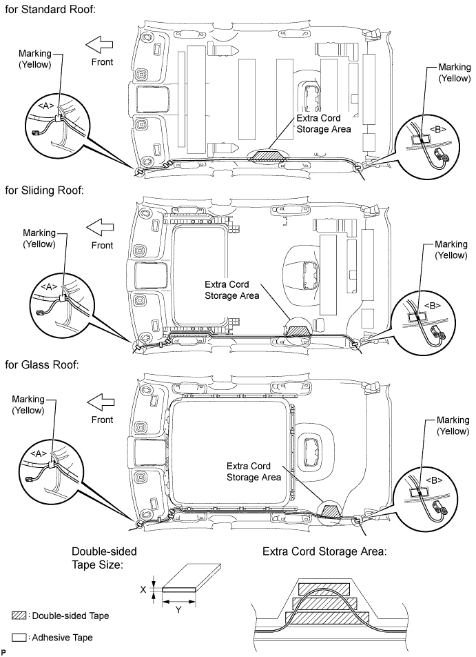
Area Dimension X 1.0 mm (0.0394 in.) Y 15.0 mm (0.591 in.)
-
-
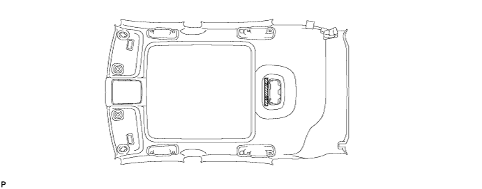
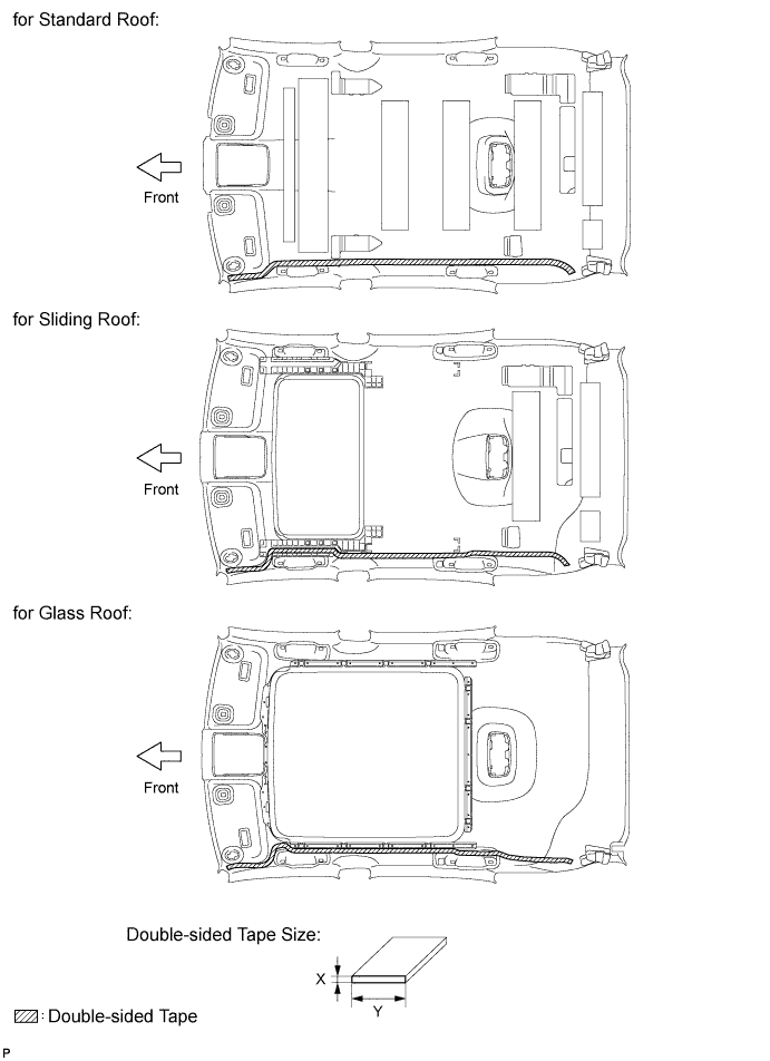
INSTALL NO. 2 ANTENNA CORD SUB-ASSEMBLY
Tech Tips
Double-sided tape and tape are not available as supply parts. If the tape still has enough adhesion to secure the roof headlining and antenna cord, reuse it. If the roof headlining has been replaced with a new one, or if the tape and/or the double-sided tape is no longer sticky, apply new tape following the procedure below.
If the double-sided tape cannot be reused:
-
Peel off the release paper from one side of new double-sided tape and apply the new double-sided tape to the position indicated in the illustration. Be careful not to touch the adhesive surface.
Area Dimension X 1.0 mm (0.0394 in.) Y 15.0 mm (0.591 in.) Note
Be sure to apply the double-sided tape carefully so that the tape will not be misaligned or come off.
-
Peel off the release paper from the double-sided tape. Be careful not to touch the adhesive surface.
-
Align the vehicle front side marking (yellow) on the No. 2 antenna cord sub-assembly with the vehicle front side tab on the roof headlining, and wrap the tape over the antenna cord to install it. (A)
Tech Tips
If the tape cannot be reused, packing tape can be used as a substitute.
-
Temporarily install the No. 2 antenna cord subassembly by placing it on the double-sided tape from the front of the vehicle to the point just before the extra cord storage area.
-
Align the vehicle rear marking (yellow) on the No. 2 antenna cord sub-assembly with the tape attachment location (scribe line) of the roof headlining, and wrap the tape over the antenna cord to install it. (B)
Tech Tips
If the tape cannot be reused, packing tape can be used as a substitute.
-
Temporarily install the No. 2 antenna cord subassembly by placing it on the double-sided tape from the rear of the vehicle to the point just before the extra cord storage area.
-
Using double-sided tape, place any excess No. 2 antenna cord sub-assembly in the extra cord storage area to finish installing the antenna cord.
Tech Tips
Attach 3 pieces of double-sided tape to the extra cord storage area as shown in the illustration.
Area Dimension X 1.0 mm (0.0394 in.) Y 15.0 mm (0.591 in.) 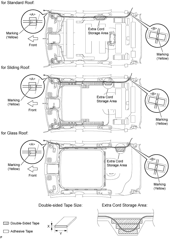
-
-
INSTALL VANITY LIGHT ASSEMBLY
-
Install the vanity light assembly Click here
Tech Tips
Use the same procedure to remove the light on the other side.
-