ROOF HEADLINING REMOVAL

-
PRECAUTION (w/ Navigation System for HDD)
Note
After the power switch is turned off, the display and navigation module display (HDD navigation system) records various types of memory and settings. As a result, after turning the power switch off, make sure to wait for the time specified in the following table before disconnecting the cable from the negative (-) battery terminal.
Waiting Time after Disconnecting Cable from Negative (-) Battery Terminal Specification Waiting Time w/o Telematics transceiver 60 sec. w/ Telematics transceiver 120 sec. -
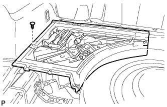
REMOVE REAR DECK FLOOR BOX
-

Remove the 3 clips and the rear deck floor box.
-
-
DISCONNECT CABLE FROM NEGATIVE BATTERY TERMINAL
Note
When disconnecting the cable, some systems need to be initialized after the cable is reconnected Click here.
-
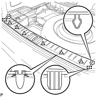
REMOVE FRONT DOOR SCUFF PLATE LH
-
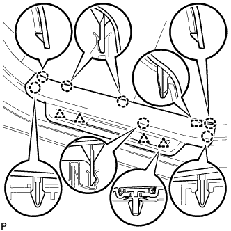
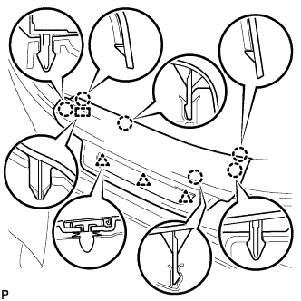
Disengage the 7 claws, 4 clips and guide, and remove the front door scuff plate LH.
Tech Tips
A part of the clip remains on the vehicle side.
-
w/ Illumination:
-
Disconnect the connector.
-
-
-
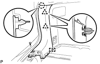
REMOVE COWL SIDE TRIM SUB-ASSEMBLY LH
-
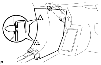
Remove the clip.
-
Disengage the 2 clips and remove the cowl side trim sub-assembly LH.
-
-
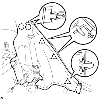
REMOVE INSTRUMENT SIDE PANEL LH
-
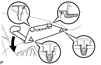
Using moulding remover A, disengage the claw and 2 clips.
-
Disengage the guide and remove the instrument side panel LH.
-
-
REMOVE FRONT PILLAR GARNISH LH
-
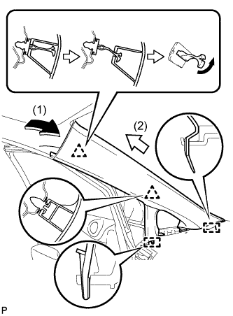
Pull the upper part of the garnish toward the inside of the cabin and disengage the garnish from the base of the 2 clips.
Tech Tips
Make the front pillar garnish LH hang down from the front pillar garnish clip.
-
Turn the end of the front pillar garnish clip 90° with needle-nosed pliers and remove it from the front pillar garnish LH.
Note
-
Front pillar garnish clips are reusable if they are not removed from the vehicle and have no damage.
-
Replace the front pillar garnish clips with new ones if they are removed from the vehicle.
Tech Tips
Tape the tips of the needle-nosed pliers before use.
-
-
Disengage the 2 guides and remove the front pillar garnish LH.
-
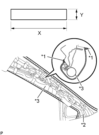
Text in Illustration *1 Adhesive Tape *2 Protective Cover *3 Curtain Shield Airbag Assembly Protect the curtain shield airbag assembly.
-
Cover the airbag with a cloth or piece of nylon and secure the ends of the cover with tape, as shown in the illustration.
Protective Cover size X 700 mm (2.30 ft.) Y 120 mm (4.72 in.) Note
Cover the curtain shield airbag with a protective cover as soon as the front pillar garnish is removed.
-
-
-
REMOVE REAR DOOR SCUFF PLATE LH
-
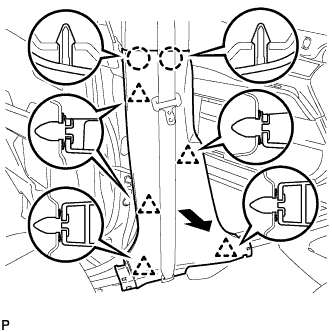
Disengage the 6 claws, 3 clips and guide, and remove the rear door scuff plate LH.
-
-
REMOVE LOWER CENTER PILLAR GARNISH LH
-
Disengage the 2 claws and 5 clips, and remove the lower center pillar garnish LH.
-
-
DISCONNECT FRONT SEAT OUTER BELT ASSEMBLY LH
-
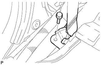
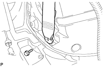
Remove the bolt and disconnect the floor end of the front seat outer belt assembly.
-
-
REMOVE CENTER PILLAR GARNISH LH
-
Remove the 2 screws.
-
Using a clip remover, disengage the clip.
-
Pass the floor anchor of the front seat outer seat belt assembly LH through the center pillar garnish LH and remove the center pillar garnish LH.
-
-
REMOVE FRONT DOOR SCUFF PLATE RH
Tech Tips
Use the same procedure for the RH side and the LH side.
-
REMOVE COWL SIDE TRIM SUB-ASSEMBLY RH
Tech Tips
Use the same procedure for the RH side and the LH side.
-
REMOVE INSTRUMENT SIDE PANEL RH
Tech Tips
Use the same procedure for the RH side and the LH side.
-
REMOVE FRONT PILLAR GARNISH RH
Tech Tips
Use the same procedure for the RH side and the LH side.
-
REMOVE REAR DOOR SCUFF PLATE RH
Tech Tips
Use the same procedure for the RH side and the LH side.
-
REMOVE LOWER CENTER PILLAR GARNISH RH
Tech Tips
Use the same procedure for the RH side and the LH side.
-
DISCONNECT FRONT SEAT OUTER BELT ASSEMBLY RH
Tech Tips
Use the same procedure for the RH side and the LH side.
-
REMOVE CENTER PILLAR GARNISH RH
Tech Tips
Use the same procedure for the RH side and the LH side.
-
REMOVE DECK BOARD SUB-ASSEMBLY
-
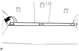
Disengage the 3 fasteners as shown in the illustration.
-
for Compact Spare Tire:
-
Remove the 2 bolts and remove the deck board sub-assembly.
-
-
for Full Size Spare Tire:
-
Remove the 2 bolts and remove the deck board sub-assembly.
-
-
-
REMOVE SPARE WHEEL COVER ASSEMBLY (for Compact Spare Tire)
-
Remove the spare wheel cover assembly.
-
-
REMOVE NO. 4 REAR FLOOR BOARD (for Compact Spare Tire)
-
Disengage the 2 guides and remove the No. 4 rear floor board.
-
-
REMOVE NO. 4 REAR FLOOR BOARD (for Full Size Spare Tire)
-
Disengage the 2 guides and remove the No. 4 rear floor board.
-
-
REMOVE NO. 3 REAR FLOOR BOARD (for Compact Spare Tire)
-
Disengage the 2 guides and remove the No. 3 rear floor board.
-
-
REMOVE NO. 3 REAR FLOOR BOARD (for Full Size Spare Tire)
-
Disengage the 2 guides and remove the No. 3 rear floor board.
-
-
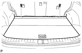
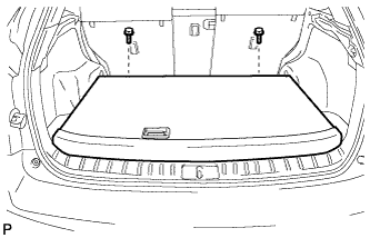
REMOVE TONNEAU COVER ASSEMBLY
-
Remove the tonneau cover assembly.
-
-
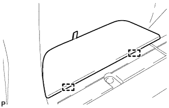
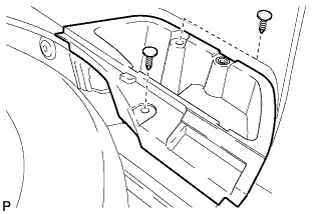
REMOVE DECK SIDE TRIM BOX LH (for Compact Spare Tire)
-
Remove the 2 clips and the deck side trim box LH.
-
-
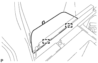
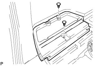
REMOVE DECK SIDE TRIM BOX LH (for Full Size Spare Tire)
-
Remove the 3 clips and the deck side trim box LH.
-
-
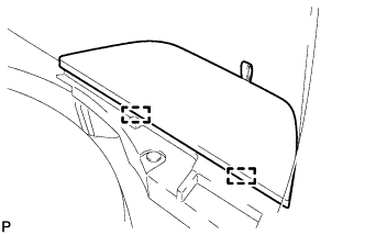
REMOVE DECK SIDE TRIM BOX RH (for Compact Spare Tire)
-
Remove the 2 clips and deck side trim box RH.
-
-
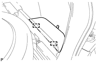
REMOVE DECK SIDE TRIM BOX RH (for Full Size Spare Tire)
-
Remove the 3 clips and the deck side trim box RH.
-
-
REMOVE FRONT DECK FLOOR BOX
-
Remove the clip and the front deck floor box.
-
-
REMOVE REAR FLOOR FINISH PLATE
-
Disengage the 2 claws, 6 clips and 2 guides, and remove the rear floor finish plate.
-
-
REMOVE REAR FLOOR FINISH SIDE PLATE LH
-
Remove the clip.
-
Disengage the claw and 2 clips.
-
Disengage the guide and remove the rear floor finish side plate LH.
-
-
REMOVE REAR SEAT ASSEMBLY LH
-
Remove the rear seat assembly LH Click here.
-
-
REMOVE REAR SEAT SIDE COVER LH
-
Remove the 2 clips.
-
Disengage the 2 claws and 3 clips, and remove the rear seat side cover LH.
Tech Tips
A part of the clip remains on the vehicle side.
-
-
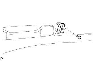
REMOVE NO. 1 LUGGAGE COMPARTMENT TRIM HOOK (for LH Side)
-
Remove the No. 1 luggage compartment trim hook as shown in the illustration.
-
-
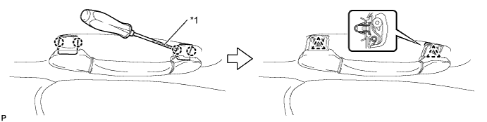
REMOVE ROPE HOOK ASSEMBLY (for LH Side)
-
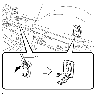
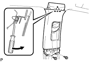
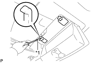
Text in Illustration *1 Protective Tape Using a screwdriver, disengage the 2 claws.
Tech Tips
Tape the screwdriver tip before use.
-
Remove the 2 bolts and the 2 rope hook assemblies.
-
-
REMOVE RECLINING REMOTE CONTROL BEZEL LH
-
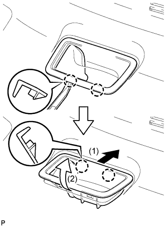
Using moulding remover A, disengage the 2 bottom claws of the reclining remote control bezel LH.
-
Lift the reclining remote control bezel LH as shown by the arrow (1) in the illustration.
-
Turn the reclining remote control bezel LH as shown by the arrow (2) in the illustration, then disengage the 2 upper claws and remove the bezel.
-
-
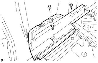
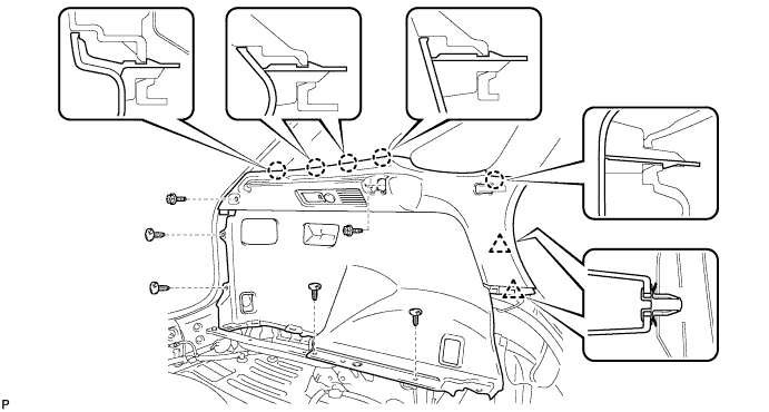
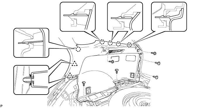
REMOVE DECK TRIM SIDE PANEL ASSEMBLY LH
-
Remove the 2 screws.
-
Remove the 4 clips.
-
Disengage the 5 claws and 2 clips.
-
Disconnect each connector and remove the deck trim side panel assembly LH.
-
-
DISCONNECT REAR SEAT OUTER BELT ASSEMBLY LH
-
Remove the bolt and disconnect the floor end of the rear seat outer belt assembly.
-
-
REMOVE ROOF SIDE INNER GARNISH ASSEMBLY LH
-
Disengage the 8 clips.
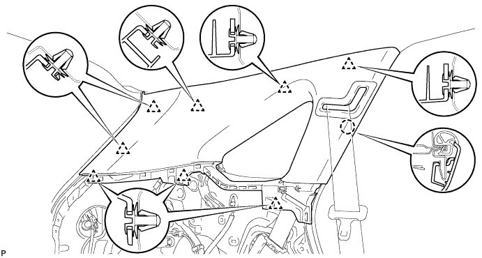
Tech Tips
A part of the clip remains on the vehicle side.
-
Pass the floor anchor of the rear seat outer seat belt assembly LH through the roof side inner garnish assembly LH and remove the roof side inner garnish assembly LH.
-
-
REMOVE REAR FLOOR FINISH SIDE PLATE RH
Tech Tips
Use the same procedure for the RH side and the LH side.
-
REMOVE REAR SEAT ASSEMBLY RH
-
Remove the rear seat assembly RH Click here.
-
-
REMOVE REAR SEAT SIDE COVER RH
Tech Tips
Use the same procedure for the RH side and the LH side.
-
REMOVE NO. 1 LUGGAGE COMPARTMENT TRIM HOOK (for RH Side)
-
Remove the No. 1 luggage compartment trim hook as shown in the illustration.
-
-
REMOVE ROPE HOOK ASSEMBLY (for RH Side)
Tech Tips
Use the same procedure for the RH side and the LH side.
-
REMOVE RECLINING REMOTE CONTROL BEZEL RH
Tech Tips
Use the same procedure for the RH side and the LH side.
-
REMOVE HEIGHT CONTROL SWITCH (w/ Air Suspension)
-
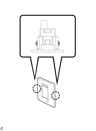
Disengage the 2 claws to remove the height control switch from the deck trim side panel assembly RH.
-
Disconnect the connector.
-
-
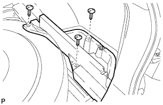
REMOVE DECK TRIM SIDE PANEL ASSEMBLY RH
-
Remove the 2 screws.
-
Remove the 5 clips.
-
Disengage the 5 claws and 2 clips.
-
Disconnect the connector and remove the deck trim side panel assembly RH.
-
-
DISCONNECT REAR SEAT OUTER BELT ASSEMBLY RH
Tech Tips
Use the same procedure for the RH side and the LH side.
-
REMOVE ROOF SIDE INNER GARNISH ASSEMBLY RH
Tech Tips
Use the same procedure for the RH side and the LH side.
-
REMOVE MAP LIGHT ASSEMBLY
-
w/ Holder:
-
Open the holder.
-
-
w/o Holder:
-
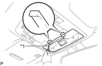
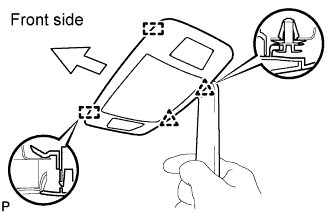
Text in Illustration *1 Protective Tape Using a screwdriver wrapped with protective tape, disengage the 2 claws and disconnect the cover.
-
-
Text in Illustration *1 Protective Tape Using a screwdriver wrapped with protective tape, disengage the 2 claws and disconnect the 2 caps.
-
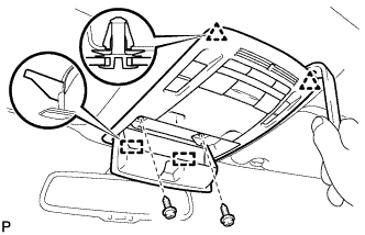
Remove the 2 screws.
-
Using a moulding remover, disengage the 2 clips and 2 guides.
-
Disconnect each connector and remove the map light assembly.
-
-
REMOVE SPOT LIGHT ASSEMBLY
-
Using a moulding remover, disengage the 2 clips and 2 guides.
-
Disconnect the connector and remove the spot light assembly.
-
-
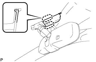
REMOVE INNER REAR VIEW MIRROR STAY HOLDER COVER (w/ EC Mirror)
-
w/o Rear View Monitor System:
-
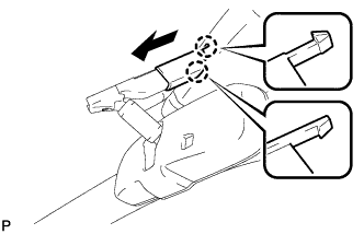
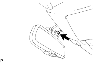
Disengage the 2 claws and slide the inner rear view mirror stay holder cover as shown in the illustration.
-
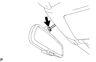
Disengage the 6 claws and remove the inner rear view mirror stay holder cover.
-
-
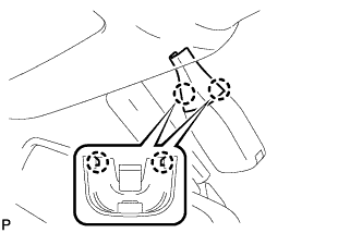
w/ Rear View Monitor System:
-
Disengage the 2 claws and slide the inner rear view mirror stay holder cover as shown in the illustration.
-
Disengage the 2 claws and remove the inner rear view mirror stay holder cover.
-
-
-
REMOVE RAIN SENSOR COVER (w/ Rain Sensor)
-
Disengage the 2 claws and remove the rain sensor cover.
-
-
REMOVE COAT HOOK
-
Remove the screw and coat hook.
Tech Tips
Use the same procedure for the RH side and the LH side.
-
-
REMOVE ASSIST GRIP SUB-ASSEMBLY
-
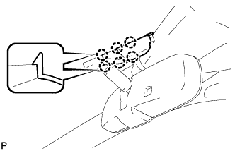
Using a screwdriver, disengage the 4 claws and remove the 2 assist grip covers.
Text in Illustration *1 Protective Tape Note
Do not forcibly pry the assist grip covers to prevent them from being deformed.
Tech Tips
Tape the screwdriver tip before use.
-
Disengage the 2 clips and remove the assist grip sub-assembly.
Tech Tips
Use the same procedure for the other 3 assist grips.
-
-
REMOVE VISOR BRACKET COVER (for LH Side)
-
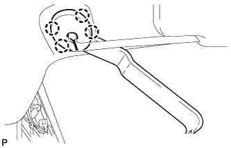
Using moulding remover C, disengage the 4 claws and remove the visor bracket cover.
-
-
REMOVE VISOR ASSEMBLY LH
-
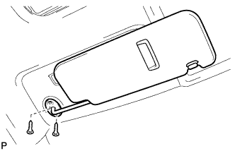
Remove the 2 screws and remove the visor assembly LH.
-
-
REMOVE VISOR BRACKET COVER (for RH Side)
Tech Tips
Use the same procedure for the RH side and the LH side.
-
REMOVE VISOR ASSEMBLY RH
Tech Tips
Use the same procedure for the RH side and the LH side.
-
REMOVE VISOR HOLDER (for LH Side)
-
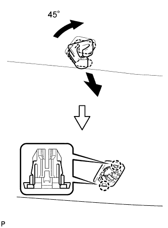
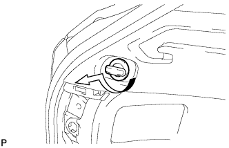
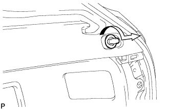
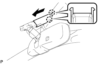
Turn the visor holder approximately 45° and pull it out as shown in the illustration.
-
Disengage the 2 claws and remove the visor holder.
-
-
REMOVE VISOR HOLDER (for RH Side)
Tech Tips
Use the same procedure for the RH side and the LH side.
-
REMOVE ROOF HEADLINING ASSEMBLY (for Standard Roof)
-
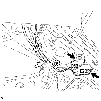
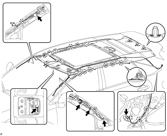
Disconnect the No. 2 antenna cord sub-assembly connectors and washer hose, and disengage the 2 claws and 3 clamps from the rear pillar RH.
-
w/ Rain Sensor:
-
Disconnect the No. 1 roof wire connector from the rain sensor.
-
-
Disconnect the No. 1 roof wire connector from the inner rear view mirror.
-
Disconnect the No. 4 antenna cord sub-assembly connector and No. 1 roof wire connectors and disengage the 2 claws from the front pillar LH.
-
Disconnect the No. 2 antenna cord sub-assembly connector and washer hose, and disengage the 2 claws from the front pillar RH.
-
Disconnect the No. 4 antenna cord sub-assembly connector and No. 1 roof wire connectors and disengage the 2 claws from the front pillar LH.
-
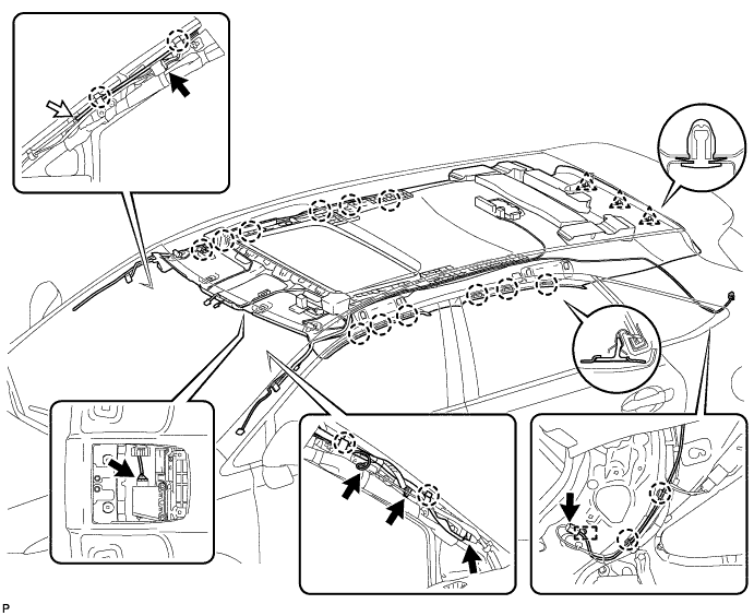
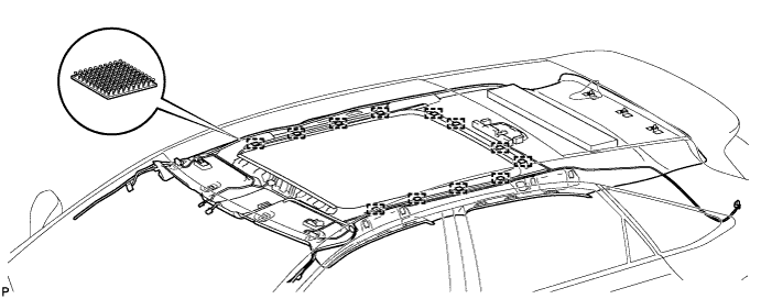
Disengage the 12 claws and 3 clips.
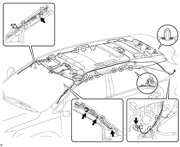
-
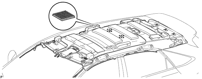
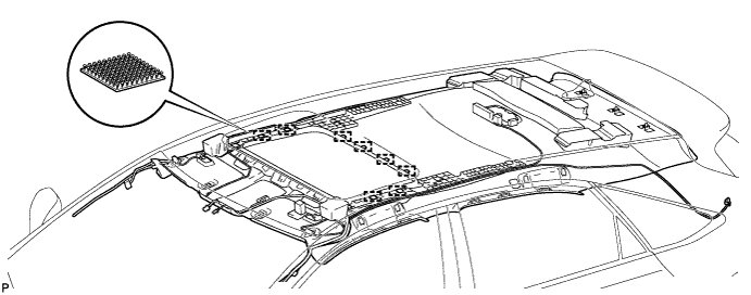
Disengage the 2 fasteners.
-
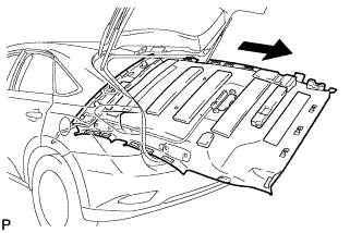
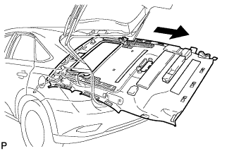
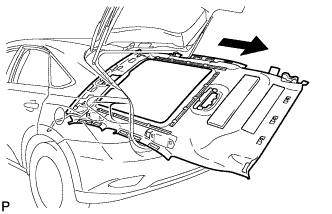
Remove the roof headlining assembly from the vehicle through the back door.
Note
Do not damage the roof headlining assembly or body interior.
-
-
REMOVE ROOF HEADLINING ASSEMBLY (for Sliding roof)
-
Disconnect the No. 2 antenna cord sub-assembly connectors and washer hose, and disengage the 2 claws and 3 clamps from the rear pillar RH.
-
w/ Rain Sensor:
-
Disconnect the No. 1 roof wire connector from the rain sensor.
-
-
Disconnect the No. 1 roof wire connector from the inner rear view mirror.
-
Disconnect the No. 4 antenna cord sub-assembly connector and No. 1 roof wire connectors and disengage the 2 claws from the front pillar LH.
-
Disconnect the No. 2 antenna cord sub-assembly connector and washer hose, and disengage the 2 claws from the front pillar RH.
-
Disconnect the No. 4 antenna cord sub-assembly connector and No. 1 roof wire connectors and disengage the 2 claws from the front pillar LH.
-
Disconnect the No. 1 roof wire connector from the sliding roof drive gear assembly.
-
Disengage the 12 claws and 3 clips.
-
Disengage the 8 fasteners.
-
Remove the roof headlining assembly from the vehicle through the back door.
Note
Do not damage the roof headlining assembly or body interior.
-
-
REMOVE ROOF HEADLINING ASSEMBLY (for Glass Roof)
-
Disconnect the No. 2 antenna cord sub-assembly connectors and washer hose, and disengage the 2 claws and 3 clamps from the rear pillar RH.
-
w/ Rain Sensor:
-
Disconnect the No. 1 roof wire connector from the rain sensor.
-
-
Disconnect the No. 1 roof wire connector from the inner rear view mirror.
-
Disconnect the No. 4 antenna cord sub-assembly connector and No. 1 roof wire connectors and disengage the 2 claws from the front pillar LH.
-
Disconnect the No. 2 antenna cord sub-assembly connector and washer hose, and disengage the 2 claws from the front pillar RH.
-
Disconnect the No. 4 antenna cord sub-assembly connector and No. 1 roof wire connectors and disengage the 2 claws from the front pillar LH.
-
Disengage the 12 claws and 3 clips.
-
Disengage the 12 fasteners.
-
Remove the roof headlining assembly from the vehicle through the back door.
Note
Do not damage the roof headlining assembly or body interior.
-
-
REMOVE FRONT DOOR OPENING TRIM WEATHERSTRIP LH
-
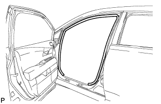
Remove the front door opening trim weatherstrip LH.
-
-
REMOVE FRONT DOOR OPENING TRIM WEATHERSTRIP RH
Tech Tips
Use the same procedure for the RH side and the LH side.
-
REMOVE REAR DOOR OPENING TRIM WEATHERSTRIP LH
-
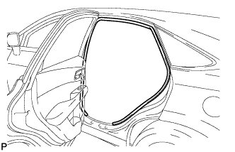
Remove the rear door opening trim weatherstrip LH.
-
-
REMOVE REAR DOOR OPENING TRIM WEATHERSTRIP RH
Tech Tips
Use the same procedure for the RH side and the LH side.