FRONT CONSOLE BOX DISASSEMBLY

-
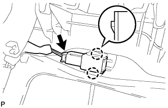
REMOVE CONSOLE COIN BOX
-
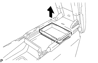
Remove the console coin box as shown in the illustration.
-
-
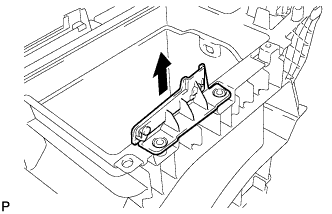
REMOVE LOWER CONSOLE BOX POCKET
-
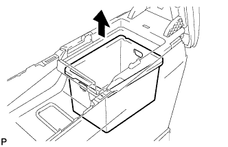
Remove the lower console box pocket as shown in the illustration.
-
-
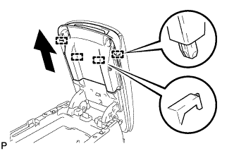
REMOVE FRONT CONSOLE UPPER PANEL GARNISH
-
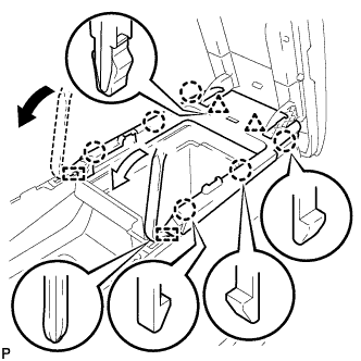
Using moulding remover A, disengage the 6 claws, 2 clips and 2 guides, and remove the front console upper panel garnish as shown in the illustration.
-
-
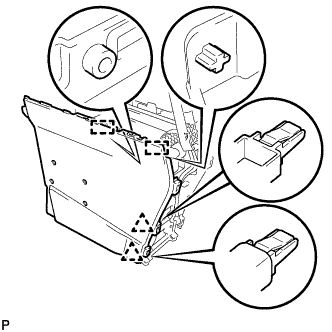
REMOVE CONSOLE COMPARTMENT DOOR LOCK SUB-ASSEMBLY
-
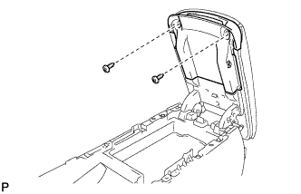
Remove the 2 screws.
-
Pull the console compartment door lock sub-assembly in the direction indicated by the arrow to disengage the 4 guides and remove the console compartment door lock sub-assembly.
-
-
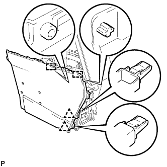
REMOVE CONSOLE COMPARTMENT DOOR SUB-ASSEMBLY
-
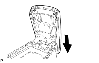
Remove the console compartment door subassembly as shown in the illustration.
-
-
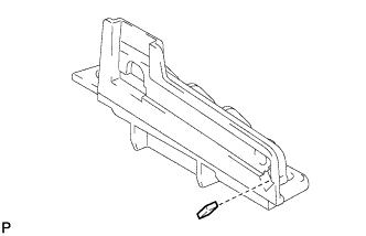
REMOVE CONSOLE BOX CUSHION
-
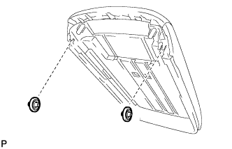
Remove the 2 console box cushions from the console compartment door.
-
-
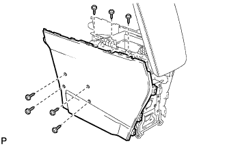
REMOVE NO. 1 UPPER BOX PLATE
-
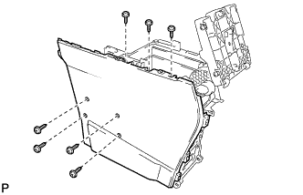
Remove the 7 screws.
-
Disengage the 2 clips and 2 guides, and remove the No. 1 side box panel.
-
Remove the No. 1 upper box plate as shown in the illustration.
-
-
REMOVE NO. 2 UPPER BOX PLATE
Tech Tips
Use the same procedure as for the No. 1 upper box plate.
-
REMOVE NO. 1 CONSOLE COMPARTMENT DOOR CUSHION
-
Remove the No. 1 console compartment door cushion from the No. 1 upper box plate.
Tech Tips
Use the same procedure for the No. 2 upper box plate and No. 1 upper box plate.
-
-
REMOVE NO. 2 CONSOLE COMPARTMENT DOOR CUSHION
-
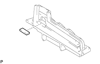
Remove the No. 2 console compartment door cushion from the No. 1 upper box plate.
Tech Tips
Use the same procedure for the No. 2 upper box plate and No. 1 upper box plate.
-
-
REMOVE REAR CONSOLE BOX WIRE
-
Remove the screw.
-
Disconnect each connector.
-
Disengage the 6 clamps and remove the rear console box wire.
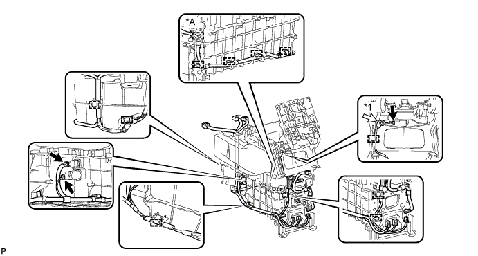
Text in Illustration *A w/ Rear Seat Entertainment System - - *1 Screw - -
-
-
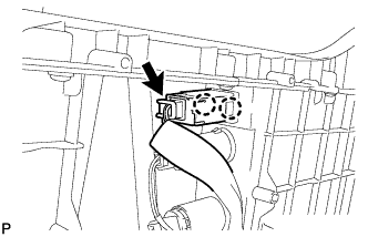
REMOVE CONSOLE BOX ILLUMINATION LIGHT ASSEMBLY
-
Disengage the 2 claws.
-
Disconnect the connector and remove the console box illumination light assembly.
-
-
REMOVE STEREO JACK ADAPTER ASSEMBLY
-
Remove the 7 screws.
-
Disengage the 2 clips and 2 guides, and remove the No. 1 side box panel.
-
Disconnect the connector.
-
Disengage the 2 claws and remove the stereo jack adapter assembly.
-
-
REMOVE POWER POINT SOCKET ASSEMBLY
-
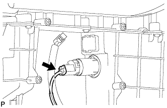
Disconnect the connector.
-
Disengage the 2 clamps.
-
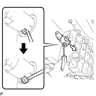
Using a screwdriver, bend back and break off the 2 claws as shown in the illustration.
Tech Tips
The power point socket cover will not be reused.
-
Remove the power point socket assembly and power point socket cover in the direction shown in the illustration.
-
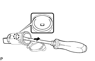
Using a screw driver, disengage the claw and remove the power point socket assembly from the power point socket cover as shown in the illustration.
-