REAR POWER OUTLET SOCKET REMOVAL

-
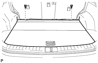
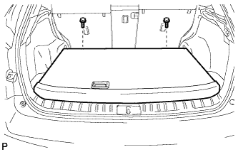
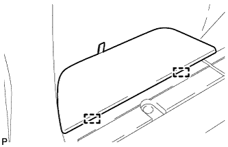
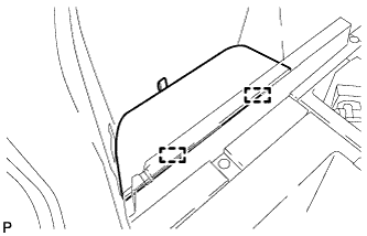
REMOVE TONNEAU COVER ASSEMBLY
-
Remove the tonneau cover assembly.
-
-
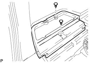
REMOVE DECK BOARD SUB-ASSEMBLY
-
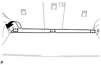
Disengage the 3 fasteners as shown in the illustration.
-
for Compact Spare Tire:
-
Remove the 2 bolts and remove the deck board sub-assembly.
-
-
for Full Size Spare Tire:
-
Remove the 2 bolts and remove the deck board sub-assembly.
-
-
-
REMOVE NO. 4 REAR FLOOR BOARD (for Compact Spare Tire)
-
Disengage the 2 guides and remove the No. 4 rear floor board.
-
-
REMOVE NO. 4 REAR FLOOR BOARD (for Full Size Spare Tire)
-
Disengage the 2 guides and remove the No. 4 rear floor board.
-
-
REMOVE REAR DECK FLOOR BOX
-

Remove the 3 clips and the rear deck floor box.
-
-
REMOVE DECK SIDE TRIM BOX LH (for Compact Spare Tire)
-
Remove the 2 clips and the deck side trim box LH.
-
-
REMOVE DECK SIDE TRIM BOX LH (for Full Size Spare Tire)
-
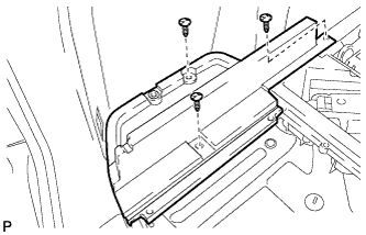
Remove the 3 clips and the deck side trim box LH.
-
-
REMOVE FRONT DECK FLOOR BOX
-
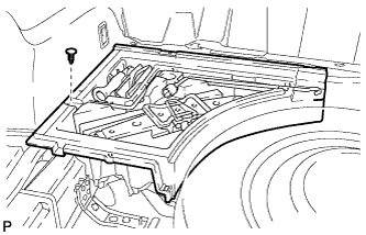
Remove the clip and the front deck floor box.
-
-
REMOVE REAR SEAT ASSEMBLY LH
-
Remove the rear seat assembly LH Click here.
-
-
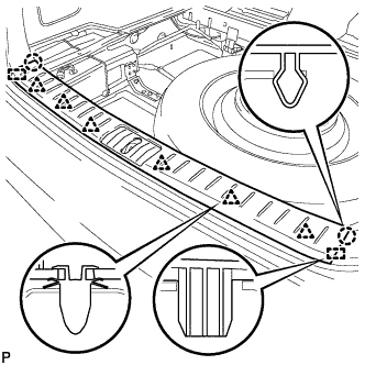
REMOVE REAR DOOR SCUFF PLATE LH
-
Disengage the 6 claws, 3 clips and guide, and remove the rear door scuff plate LH.
-
-
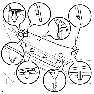
REMOVE REAR FLOOR FINISH PLATE
-
Disengage the 2 claws, 6 clips and 2 guides, and remove the rear floor finish plate.
-
-
REMOVE REAR FLOOR FINISH SIDE PLATE LH
-
Remove the clip.
-
Disengage the claw and 2 clips.
-
Disengage the guide and remove the rear floor finish side plate LH.
-
-
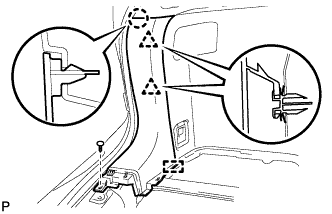
REMOVE REAR SEAT SIDE COVER LH
-
Remove the 2 clips.
-
Disengage the 2 claws and 3 clips, and remove the rear seat side cover LH.
Tech Tips
A part of the clip remains on the vehicle side.
-
-
REMOVE NO. 1 LUGGAGE COMPARTMENT TRIM HOOK LH
-
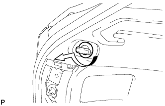
Remove the No. 1 luggage compartment trim hook as shown in the illustration.
-
-
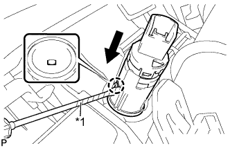
REMOVE ROPE HOOK ASSEMBLY LH
-
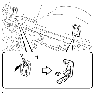
Text in Illustration *1 Protective Tape Using a screwdriver, disengage the 2 claws.
Tech Tips
Tape the screwdriver tip before use.
-
Remove the 2 bolts and the 2 rope hook assemblies.
-
-
REMOVE RECLINING REMOTE CONTROL BEZEL LH
-
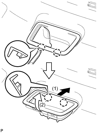
Using moulding remover A, disengage the 2 bottom claws of the reclining remote control bezel LH.
-
Lift the reclining remote control bezel LH as shown by the arrow (1) in the illustration.
-
Turn the reclining remote control bezel LH as shown by the arrow (2) in the illustration, then disengage the 2 upper claws and remove the bezel.
-
-
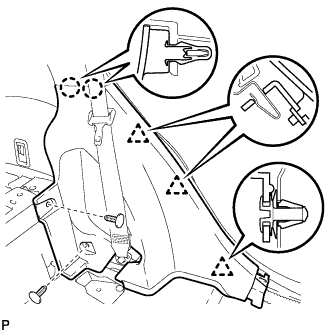
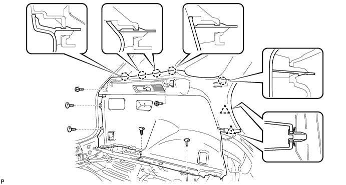
REMOVE DECK TRIM SIDE PANEL ASSEMBLY LH
-
Remove the 2 screws.
-
Remove the 4 clips.
-
Disengage the 5 claws and 2 clips.
-
Disconnect each connector and remove the deck trim side panel assembly LH.
-
-
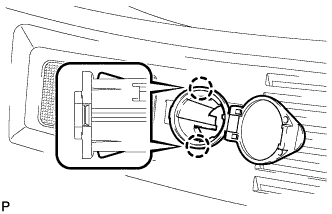
REMOVE REAR POWER POINT SOCKET ASSEMBLY
-
Using a screwdriver, disengage the claw and remove the rear power point socket assembly.
Tech Tips
Tape a screwdriver tip before use.
Text in Illustration *1 Protective Tape
-
-
REMOVE REAR POWER OUTLET SOCKET COVER
-
Disengage the 2 claws and remove the rear power outlet socket cover.
-