HEATER WATER PUMP REMOVAL

-
PRECAUTION (w/ Navigation System for HDD)
Note
After the power switch is turned off, the display and navigation module display (HDD navigation system) records various types of memory and settings. As a result, after turning the power switch off, make sure to wait for the time specified in the following table before disconnecting the cable from the negative (-) battery terminal.
Waiting Time before Disconnecting Cable from Negative (-) Battery Terminal Specification Waiting Time w/o Telematics transceiver 60 sec. w/ Telematics transceiver 120 sec. -
REMOVE REAR DECK FLOOR BOX
-

Remove the 3 clips and the rear deck floor box.
-
-
DISCONNECT CABLE FROM NEGATIVE BATTERY TERMINAL
Note
When disconnecting the cable, some systems need to be initialized after the cable is reconnected Click here.
-
REMOVE BATTERY SERVICE HOLE COVER
-
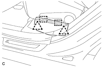
Disengage the 2 clips and 2 guides, and remove the battery service hole cover.
Tech Tips
Because these are 2-piece clips, one side will remain in the bracket when they are being removed.
-
-
REMOVE SERVICE PLUG GRIP
CAUTION:
-
Remove the service plug grip to interrupt a high voltage circuit at the time of the check.
-
Keep the removed service plug grip in your pocket to prevent other technicians from accidentally reconnecting it while you are servicing the vehicle.
-
All the high voltage wiring connectors are orange colored.
-
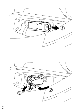
Wear insulated gloves. Remove the service plug grip after sliding the lever of the service plug grip.
CAUTION:
-
Keep the removed service plug grip in your pocket to prevent other technicians from accidentally reconnecting it while you are servicing the vehicle.
-
After disconnecting the service plug grip, wait for at least 10 minutes before touching any of the high-voltage connectors or terminals.
Tech Tips
Waiting for at least 10 minutes is required to discharge the high-voltage capacitor inside the inverter with converter assembly.
-
-
-
REMOVE AIR CLEANER ASSEMBLY
Tech Tips
Refer to the procedure for Remove Air Cleaner Assembly Click here.
-
CHECK TERMINAL VOLTAGE
-
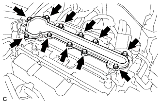
Remove the 11 bolts and inverter terminal cover.
CAUTION:
Wear insulating gloves.
Note
Make sure to pull the inverter cover straight up, as a connector is connected to the bottom of the cover.
-
Check the terminal voltage Click here.
CAUTION:
Wear insulating gloves.
-
Temporarily install the inverter cover with the 11 bolts to prevent any foreign objects or water drops from entering the inverter with converter assembly.
Note
Make sure to pull the inverter cover straight up, as a connector is connected to the bottom of the cover.
-
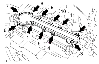
Using several steps, install and tighten the 11 bolts uniformly in the sequence shown in the illustration.
CAUTION:
Wear insulating gloves.
Note
-
Make sure that the interlock are fully engaged.
-
Do not allow any foreign objects or water drops to enter the inverter with converter assembly.
- Torque:
- 8.0 N*m { 82 kgf*cm, 71 in.*lbf }
-
-
-
REMOVE HEATER WATER PUMP ASSEMBLY
-
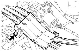
Remove the bolt and disengage the wire harness.
CAUTION:
Wear insulating gloves.
-
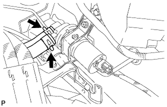
Using pliers, grip the claws of the clip, slide the clip, and disconnect the 2 heater water hoses.
Note
-
Do not apply any excessive force to the heater water hoses.
-
Prepare a drain pan or cloth for when the cooling water leaks.
-
-
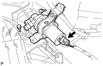
Disconnect the connector.
-
Remove the 2 bolts and heater water pump assembly.
-