SOLAR SENSOR INSPECTION

-
INSPECT SOLAR SENSOR
-
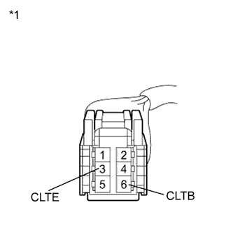
Text in Illustration *1 Front view of wire harness connector
(to Solar Sensor)
Disconnect the solar sensor connector.
-
Measure the voltage according to the value(s) in the table below.
Standard Voltage Tester Connection Condition Specified Condition 6 (CLTB) - 3 (CLTE) Power switch off Below 1 V 6 (CLTB) - 3 (CLTE) Power switch on (IG) 11 to 14 V If the voltage is not as specified, repair or replace the wire harness or connector.
-
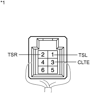
Text in Illustration *1 Component with harness connected
(Solar Sensor)
Reconnect the solar sensor connector.
-
Turn the power switch on (IG).
-
Measure the voltage according to the value(s) in the table below.
Standard Voltage Tester Connection Condition Specified Condition 1 (TSL) - 3 (CLTE) Sensor is exposed to electric light 0.8 to 4.3 V 1 (TSL) - 3 (CLTE) Sensor is covered with a cloth Below 0.8 V 2 (TSR) - 3 (CLTE) Sensor is exposed to electric light 0.8 to 4.3 V 2 (TSR) - 3 (CLTE) Sensor is covered with a cloth Below 0.8 V
-
*2: for LHD
-
*3: for RHD
Note
-
The connection procedure for using a digital tester such as a TOYOTA electrical tester is shown above. When using an analog tester, connect a negative (-) lead to terminal 2*2 (1*3) and a positive (+) lead to terminal 6 of the solar sensor.
-
While using the battery during inspection, do not bring the positive and negative tester probes too close to each other as a short circuit may occur.
Tech Tips
-
Use an incandescent light for inspection. Bring it within about 30 cm (11.8 in.) of the solar sensor.
-
As the inspection light is moved away from the sensor, the voltage decreases.
If the voltage is not as specified, replace the solar sensor.
-
-