CONDENSER REMOVAL

-
PRECAUTION (w/ Navigation System for HDD)
Note
After the power switch is turned off, the display and navigation module display (HDD navigation system) records various types of memory and settings. As a result, after turning the power switch off, make sure to wait for the time specified in the following table before disconnecting the cable from the negative (-) battery terminal.
Waiting Time before Disconnecting Cable from Negative (-) Battery Terminal Specification Waiting Time w/o Telematics transceiver 60 sec. w/ Telematics transceiver 120 sec. -
RECOVER REFRIGERANT FROM REFRIGERATION SYSTEM
-
Turn the A/C switch on.
-
Operate the A/C with the setting temperature at 25°C (77°F) and the blower level at LO for 10 minutes to circulate the refrigerant. This causes most of the compressor oil from the various components of the A/C system to collect in the A/C compressor.
-
Turn the power switch off.
-
Recover the refrigerant from the A/C system using a refrigerant recovery unit.
-
-
REMOVE REAR DECK FLOOR BOX
-

Remove the 3 clips and the rear deck floor box.
-
-
DISCONNECT CABLE FROM NEGATIVE BATTERY TERMINAL
Note
When disconnecting the cable, some systems need to be initialized after the cable is reconnected Click here.
-
REMOVE ENGINE ROOM SIDE COVER
-
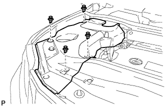
Remove the 4 clips and engine room side cover.
-
-
REMOVE ENGINE ROOM SIDE COVER LH
-
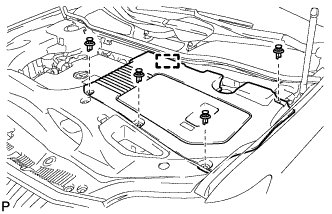
Remove the 4 clips.
-
Disengage the guide and remove the engine room side cover LH.
-
-
REMOVE COOL AIR INTAKE DUCT SEAL
-
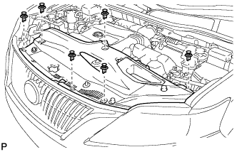
Remove the 6 clips and cool air intake duct seal.
-
-
REMOVE HOOD CENTER CUSHION
-
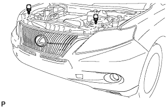
Remove the 2 hood center cushions.
-
-
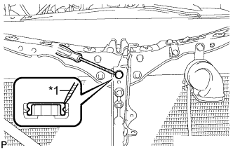
REMOVE FRONT BUMPER ASSEMBLY
-
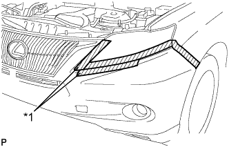
Text in Illustration *1 Protective Tape Put protective tape around the front bumper assembly.
Tech Tips
Use the same procedure for the RH side and LH side.
-
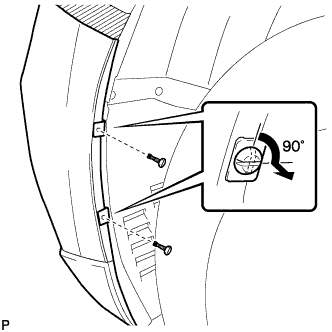
Using a screwdriver, turn the pins 90 degrees and remove the 2 pin hold clips.
Tech Tips
Use the same procedure for the RH side and LH side.
-
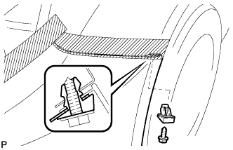
Remove the screw and front bumper seal bracket.
Tech Tips
Use the same procedure for the RH side and LH side.
-
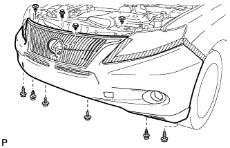
Remove the 2 bolts and 2 screws.
-
Using a clip remover, remove the 6 clips.
-
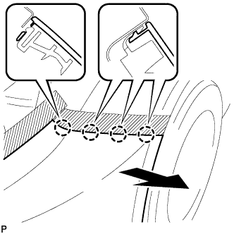
Disengage the 4 claws and remove the front bumper assembly.
Tech Tips
Use the same procedure for the RH side and LH side.
-
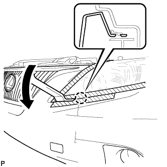
Using a moulding remover, disengage the claw.
Tech Tips
Use the same procedure for the RH side and LH side.
-
Disconnect the fog light connector.
-
Disconnect the No. 1 ultrasonic sensor connector. (w/ LEXUS Parking Assist-sensor System)
-
Disconnect the headlight cleaner hose.
Note
Prepare a drain pan or a piece of cloth in case washer fluid leaks.
-
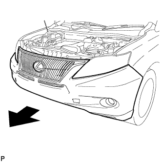
Remove the front bumper assembly as shown in the illustration.
-
-
REMOVE MILLIMETER WAVE RADAR SENSOR ASSEMBLY (w/ Dynamic Radar Cruise Control System)
-
Disconnect the connector.
-
Remove the 3 bolts and the millimeter wave radar sensor assembly.
-
-
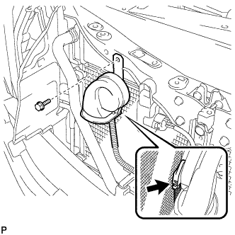
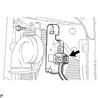
REMOVE LOW PITCHED HORN ASSEMBLY
-
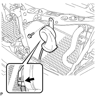
Disconnect the connector.
-
Remove the bolt and low pitched horn assembly.
-
-
REMOVE HOOD LOCK CONTROL CABLE COVER (for LHD)
-
Remove the 3 screws.
-
Disengage the clamp and remove the hood lock control cable cover.
-
-
REMOVE HOOD LOCK CONTROL CABLE COVER (for RHD)
-
Remove the 3 screws.
-
Disengage the clamp and remove the hood lock control cable cover.
-
-
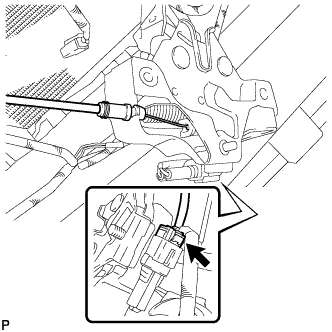
REMOVE HOOD LOCK ASSEMBLY (for LHD)
-
Text in Illustration *1 Protective Tape Using a screwdriver, remove the hood lock nut cap.
Tech Tips
Tape the screwdriver tip before use.
-
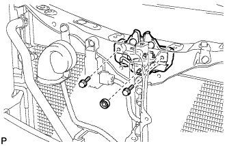
Remove the 2 bolts and hood lock nut.
-
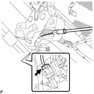
Disconnect the connector.
-
Disconnect the hood lock control cable and remove the hood lock assembly.
-
-
REMOVE HOOD LOCK ASSEMBLY (for RHD)
-
Text in Illustration *1 Protective Tape Using a screwdriver, remove the hood lock nut cap.
Tech Tips
Tape the screwdriver tip before use.
-
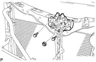
Remove the 2 bolts and hood lock nut.
-
Disconnect the connector.
-
Disconnect the hood lock control cable and remove the hood lock assembly.
-
-
REMOVE HIGH PITCHED HORN ASSEMBLY
-
Disconnect the connector.
-
Remove the bolt and high pitched horn assembly.
-
-
REMOVE SMOG VENTILATION SENSOR (w/ Smog Ventilation Sensor)
-
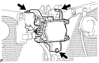
Disconnect the connector.
-
Remove the bolt
-
Disengage the guide and remove the smog ventilation sensor.
-
-
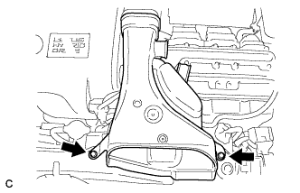
REMOVE INTAKE AIR RESONATOR SUB-ASSEMBLY
-
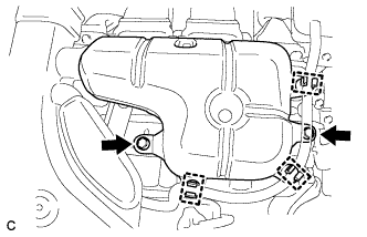
Remove the 3 clamps and Disconnect the water hose from the intake air resonator sub-assembly.
-
Remove the 2 bolts and intake air resonator sub-assembly from the inverter with converter assembly.
-
-
REMOVE NO. 2 AIR CLEANER INLET
-
Remove the 2 bolts and inlet No. 2 air cleaner.
-
-
REMOVE NO. 3 INVERTER BRACKET
-
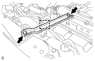
Disconnect the water hose with the clamp from the No. 3 inverter bracket.
-
Remove the 2 bolts and No. 3 inverter bracket.
-
-
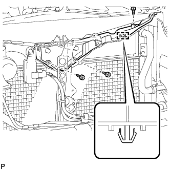
REMOVE HOOD LOCK SUPPORT SUB-ASSEMBLY
-
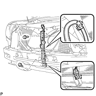
Disengage each clamp.
-
Remove the 2 bolts and hood lock support subassembly.
-
-
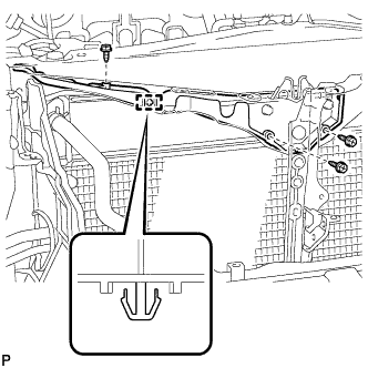
REMOVE UPPER RADIATOR SUPPORT
-
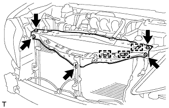
Disconnect the 3 clamps of the hood lock control cable and remove the 5 bolts and upper radiator support.
-
-
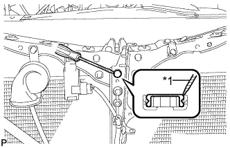
DISCONNECT DISCHARGE TUBE SUB-ASSEMBLY
-
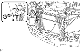
Remove the bolt and disconnect the discharge tube sub-assembly.
-
Remove the O-ring from the discharge tube subassembly.
Note
Seal the openings of the disconnected parts using vinyl tape to prevent entry of moisture and foreign matter.
-
-
DISCONNECT AIR CONDITIONING TUBE AND ACCESSORY ASSEMBLY
-
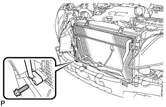
Remove the bolt and disconnect the air conditioning tube and accessory assembly.
-
Remove the O-ring from the air conditioning tube and accessory assembly.
Note
Seal the openings of the disconnected parts using vinyl tape to prevent entry of moisture and foreign matter.
-
-
DISCONNECT INLET HYBRID RADIATOR HOSE
-
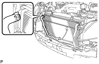
Using pliers, grip the claws of the clip and slide the clip to disconnect the inlet hybrid radiator hose.
Note
-
Do not apply excessive force to the inlet hybrid radiator hose.
-
Prepare a drain pan or cloth in case the coolant leaks.
-
-
-
DISCONNECT OUTLET HYBRID RADIATOR HOSE
-
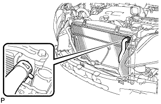
Using pliers, grip the claws of the clip and slide the clip to disconnect the outlet hybrid radiator hose.
Note
-
Do not apply excessive force to the outlet hybrid radiator hose.
-
Prepare a drain pan or cloth in case the coolant leaks.
-
-
-
REMOVE COOLER CONDENSER ASSEMBLY
Tech Tips
A 2-bolt type radiator can be used in place of a 4-bolt type radiator.
-
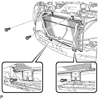
Remove the 4 bolts and cooler condenser assembly with the radiator assembly.
-
Radiator (2-bolt type):
-
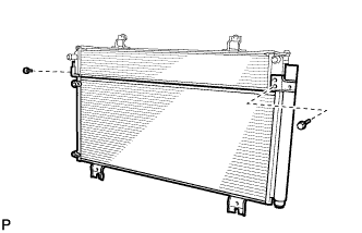
Remove the 2 bolts and cooler condenser assembly from the radiator assembly.
-
-
Radiator (4-bolt type):
-
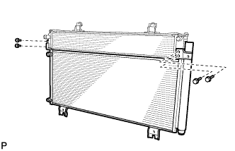
Remove the 4 bolts and cooler condenser assembly from the radiator assembly.
-
-