COMPRESSOR REMOVAL

-
PRECAUTION
Note
After turning the power switch off, waiting time may be required before disconnecting the cable from the negative (-) auxiliary battery terminal. Therefore, make sure to read the disconnecting the cable from the negative (-) auxiliary battery terminal notices before proceeding with work Click here.
-
RECOVER REFRIGERANT FROM REFRIGERATION SYSTEM
-
Turn the A/C switch on.
-
Operate the A/C with the setting temperature at 25°C (77°F) and the blower level at LO for 10 minutes to circulate the refrigerant. This causes most of the compressor oil from the various components of the A/C system to collect in the A/C compressor.
-
Turn the power switch off.
-
Recover the refrigerant from the A/C system using a refrigerant recovery unit.
-
-
REMOVE REAR DECK FLOOR BOX
-

Remove the 3 clips and the rear deck floor box.
-
-
DISCONNECT CABLE FROM NEGATIVE AUXILIARY BATTERY TERMINAL
Note
When disconnecting the cable, some systems need to be initialized after the cable is reconnected Click here.
-
REMOVE BATTERY SERVICE HOLE COVER
-
Disengage the 2 clips and 2 guides, and remove the battery service hole cover.
Tech Tips
Because these are 2-piece clips, one side will remain in the bracket when they are being removed.
-
-
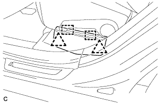
REMOVE SERVICE PLUG GRIP
CAUTION:
-
Remove the service plug grip to interrupt a high voltage circuit at the time of the check.
-
Keep the removed service plug grip in your pocket to prevent other technicians from accidentally reconnecting it while you are servicing the vehicle.
-
All the high voltage wiring connectors are orange colored.
-
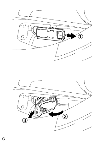
Wear insulated gloves. Remove the service plug grip after sliding the lever of the service plug grip.
CAUTION:
-
Keep the removed service plug grip in your pocket to prevent other technicians from accidentally reconnecting it while you are servicing the vehicle.
-
After disconnecting the service plug grip, wait for at least 10 minutes before touching any of the high-voltage connectors or terminals.
Tech Tips
Waiting for at least 10 minutes is required to discharge the high-voltage capacitor inside the inverter with converter assembly.
-
-
-
REMOVE RADIATOR ASSEMBLY AND FAN ASSEMBLY WITH MOTOR
Tech Tips
Refer to the procedure for Remove No. 2 Radiator Assembly Click here.
-
CHECK TERMINAL VOLTAGE
-
Remove the inverter terminal cover Click here.
-
Check the terminal voltage Click here.
-
Install the inverter terminal cover Click here.
-
-
DISCONNECT SUCTION HOSE SUB-ASSEMBLY
-
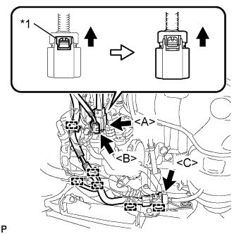
Text in Illustration *1 Green-colored Lock Release the green-colored lock and disconnect the connector <A> as shown in the illustration.
CAUTION:
Wear insulated gloves.
Note
Insulate the connector by sealing it with tape.
-
Disconnect each connector <B>, <C>.
-
Disengage each clamp.
-
Remove the bolt.
-
Disengage the clamp and disconnect the suction hose sub-assembly from the electric inverter compressor assembly.
-
Remove the O-ring from the suction hose sub-assembly.
Note
Seal the openings of the disconnected parts using vinyl tape to prevent entry of moisture and foreign matter.
-
-
DISCONNECT DISCHARGE HOSE SUB-ASSEMBLY
-
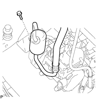
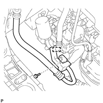
Remove the bolt and disconnect the discharge hose sub-assembly from the electric inverter compressor assembly.
-
Remove the O-ring from the discharge hose sub-assembly.
Note
Seal the openings of the disconnected parts using vinyl tape to prevent entry of moisture and foreign matter.
-
-
REMOVE ELECTRIC INVERTER COMPRESSOR ASSEMBLY
-
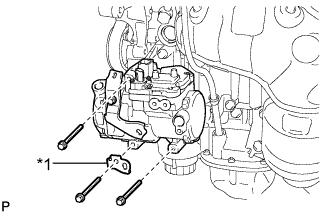
Text in Illustration *1 Bracket Remove the 3 bolts, bracket and electric inverter compressor assembly.
-
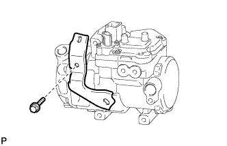
Remove the bolt and bracket from the electric inverter compressor assembly.
-