AIR CONDITIONING UNIT INSTALLATION

-
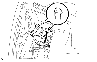
INSTALL AIR CONDITIONING UNIT ASSEMBLY
-
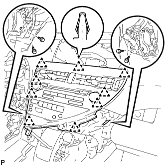
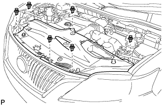
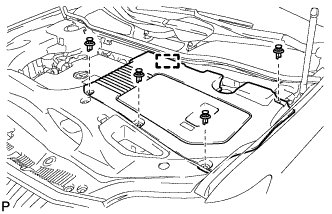
Install the air conditioning unit assembly with the 3 bolts in the order shown in the illustration.
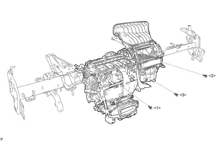
- Torque:
- 9.8 N*m { 100 kgf*cm, 87 in.*lbf }
Note
Tighten the bolts in the order shown in the illustration to install the air conditioning unit assembly.
-
-
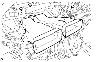
INSTALL NO. 1 AIR DUCT SUB-ASSEMBLY
-
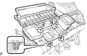
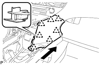
Engage the 4 claws to install the No. 1 air duct sub-assembly.
-
-
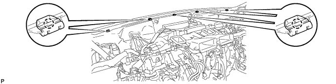
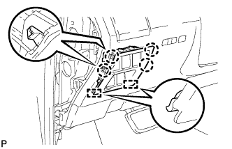
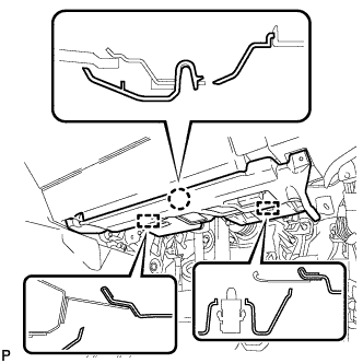
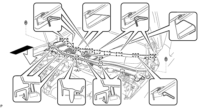
INSTALL INSTRUMENT PANEL REINFORCEMENT ASSEMBLY WITH AIR CONDITIONING UNIT ASSEMBLY
-
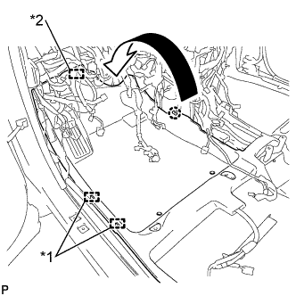
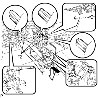
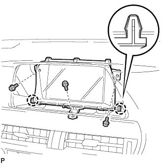
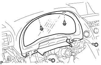
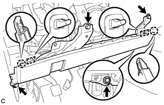
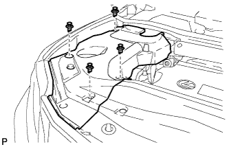
Using a "TORX" socket wrench (T40), install the instrument panel reinforcement assembly with the 5 "TORX" bolts in the order shown in the illustration.
- Torque:
- 20 N*m { 204 kgf*cm, 15 ft.*lbf }
Note
Tighten the bolts in the order shown in the illustration to install the reinforcement assembly.
-
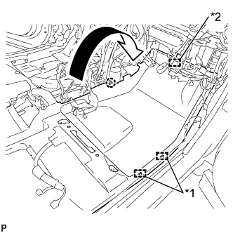
Install the 5 instrument panel safety pad caps.
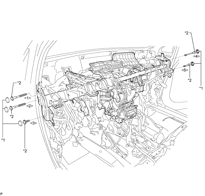
Text in Illustration *1 Instrument Panel Safety Pad Cap *2 "TORX" Bolt -
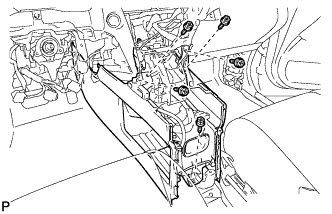
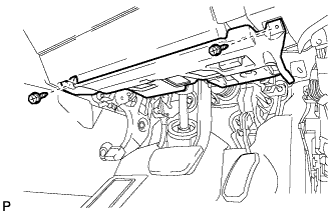
Install the 2 bolts and 2 caps from to engine compartment side.
- Torque:
- 20 N*m { 204 kgf*cm, 15 ft.*lbf }
-
Install the instrument panel reinforcement assembly with air conditioning unit assembly with the nut.
- Torque:
- 9.8 N*m { 100 kgf*cm, 87 in.*lbf }
-
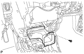
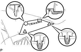
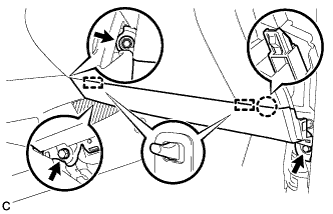
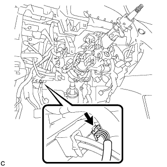
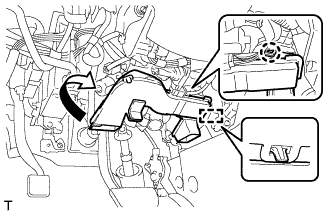
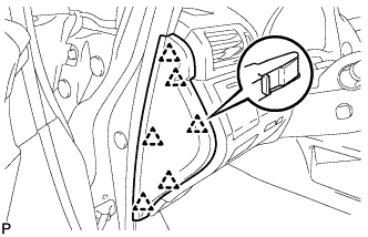
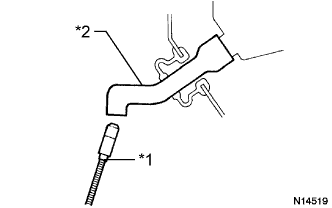
Connect the cooler drain hose as shown in the illustration.
Note
Connect the cooler drain hose firmly to prevent water leaks.
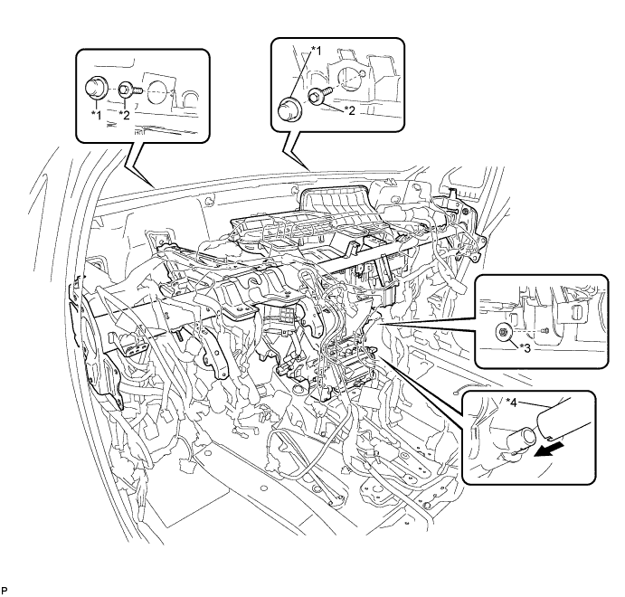
Text in Illustration *1 Cap *2 Bolt *3 Nut *4 Cooler Drain hose -
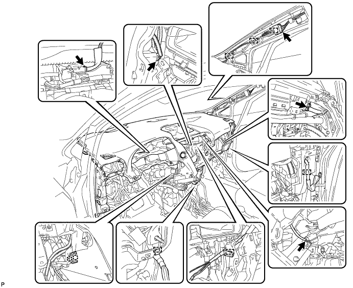
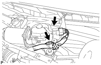
Engage each clamp.
-
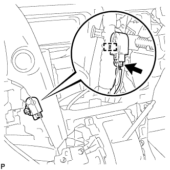
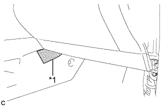
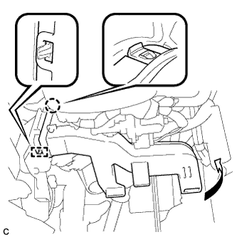
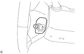
Install the bolt and connect the earth wire.
- Torque:
- 8.4 N*m { 86 kgf*cm, 74 in.*lbf }
-
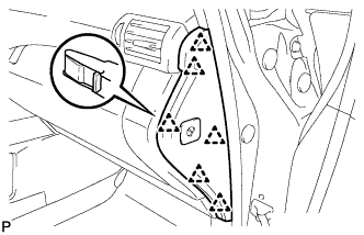
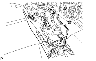
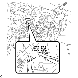
Connect the connector holder with the nut.
- Torque:
- 5.5 N*m { 56 kgf*cm, 49 in.*lbf }
-
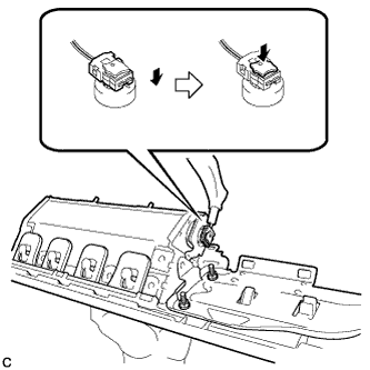
Connect the connector.
-
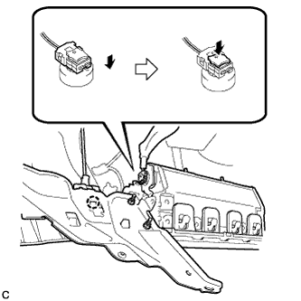
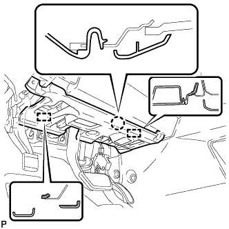
Connect the blower motor connector.
-
Connect the 2 air conditioning ECU connectors.
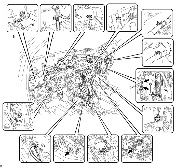
Text in Illustration *1 Blower Motor Connector *2 Air Conditioning ECU Connector *3 Nut *4 Connector Holder *5 Bolt *6 Earth Wire -
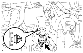
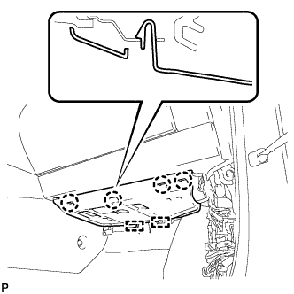
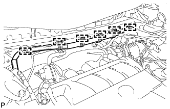
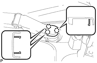
Engage each clamp.
-
Connect the earth wire with the bolt.
- Torque:
- 8.4 N*m { 86 kgf*cm, 74 in.*lbf }
-
Connect each connector.
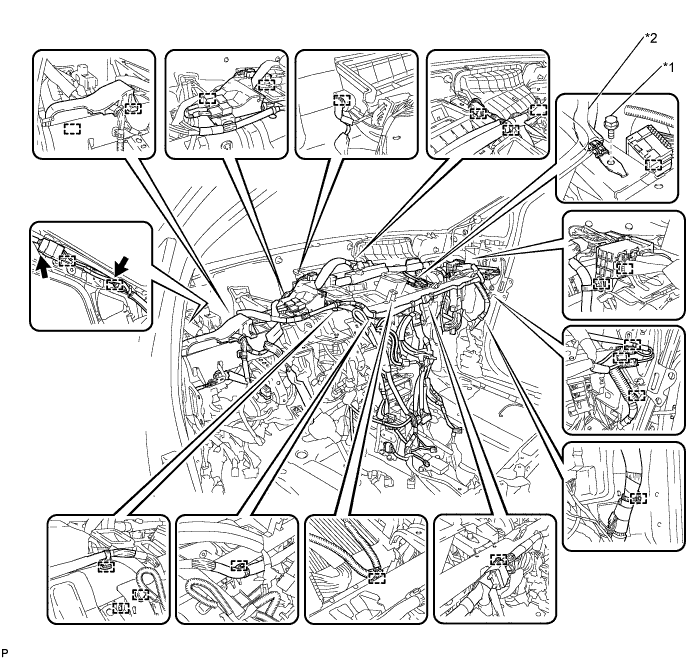
Text in Illustration *1 Bolt *2 Earth Wire
-
-
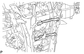
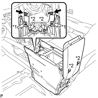
INSTALL NO. 2 INSTRUMENT PANEL BRACE SUB-ASSEMBLY
-
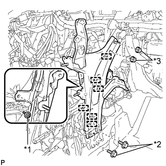
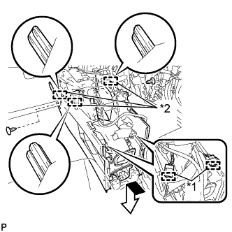
Text in Illustration *1 Screw *2 Bolt *3 Nut Install the 2 bolts and 2 nuts.
- Torque:
- Bolt
- 20 N*m { 204 kgf*cm, 15 ft.*lbf }
- Nut
- 20 N*m { 204 kgf*cm, 15 ft.*lbf }
-
Install the No. 2 instrument panel brace sub-assembly with the screw.
-
Engage each clamp.
-
-
INSTALL NO. 1 INSTRUMENT PANEL BRACE SUB-ASSEMBLY
-
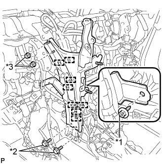
Text in Illustration *1 Screw *2 Bolt *3 Nut Install the 2 bolts and 2 nuts.
- Torque:
- Bolt
- 20 N*m { 204 kgf*cm, 15 ft.*lbf }
- Nut
- 20 N*m { 204 kgf*cm, 15 ft.*lbf }
-
Install the No. 1 instrument panel brace sub-assembly with the screw.
-
Engage each clamp.
-
-
INSTALL NO. 5 INSTRUMENT PANEL BRACKET (w/o Navigation System for HDD)
-
Install the 2 No. 5 instrument panel brackets.
-
-
INSTALL CENTER HEATER TO REGISTER SUB DUCT
-
Install the center heater to register sub duct with the 3 clips.
-
-
INSTALL REAR NO. 3 AIR DUCT
-
Engage the 2 claws to install the rear No. 3 air duct.
-
-
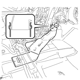
INSTALL REAR NO. 4 AIR DUCT
-
Engage the claw to install the rear No. 4 air duct.
-
Install the clip.
-
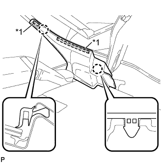
Engage the claw and 2 clamps.
-
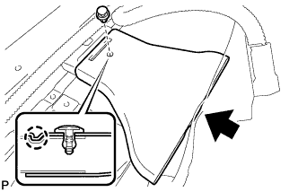
Engage the fastener to install the floor carpet to the original position.
Text in Illustration *1 Clamp *2 Fastener
-
-
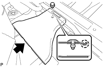
INSTALL FRONT FLOOR CAUTION PLATE COVER
-
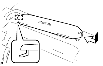
Engage the guide as shown in the illustration.
-
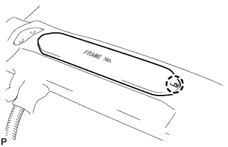
Engage the claw to install the frame number cover.
-
-
INSTALL REAR NO. 1 AIR DUCT
-
Engage the 2 claws to install the rear No. 1 air duct.
-
Engage the clamp.
-
-
INSTALL REAR NO. 2 AIR DUCT
-
Engage the claw to install the rear No. 2 air duct.
-
Install the clip.
-
Engage the claw and 2 clamps.
-
Engage the fastener to install the floor carpet to the original position.
Text in Illustration *1 Clamp *2 Fastener
-
-
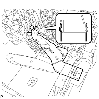
INSTALL ECU INTEGRATION BOX
-
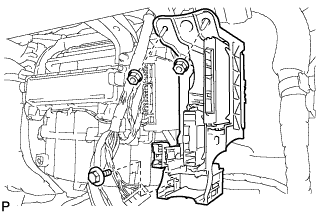
Install the ECU integration box with the bolt and 2 nuts.
- Torque:
- 5.5 N*m { 56 kgf*cm, 49 in.*lbf }
-
-
INSTALL DISPLAY AND NAVIGATION MODULE DISPLAY WITH BRACKET (w/ Navigation System for HDD)
-
Connect each connector.
-
Install the display and navigation module display with bracket as shown in the illustration.
-
-
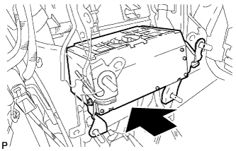
INSTALL CLEARANCE WARNING BUZZER
-
Engage the clamp to install the clearance warning buzzer.
-
Connect the connector.
-
-
INSTALL TURN SIGNAL FLASHER ASSEMBLY
-
Connect the connector.
-
Engage the clamp to install the turn signal flasher assembly.
-
-
INSTALL POWER STEERING ECU ASSEMBLY
for LHD Click here
for RHD Click here
-
INSTALL INSTRUMENT PANEL JUNCTION BLOCK ASSEMBLY (for LHD)
-
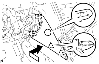
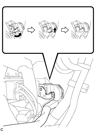
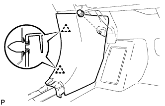
Engage the claw to connect the connector as shown in the illustration.
-
Engage the 2 claws to lock the connector lock as shown in the illustration.
-
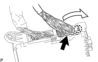
Engage the claw to connect the connector as shown in the illustration.
-
Install the instrument panel junction block assembly with the 2 nuts.
- Torque:
- 8.0 N*m { 82 kgf*cm, 71 in.*lbf }
-
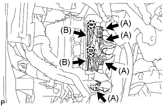
Connect the 4 connectors (A).
-
Engage the 2 claws to connect the 2 connectors (B).
-
Connect the 4 connectors.
-
-
INSTALL INSTRUMENT PANEL JUNCTION BLOCK ASSEMBLY (for RHD)
-
Engage the claw to connect the connector as shown in the illustration.
-
Engage the 2 claws to lock the connector lock as shown in the illustration.
-
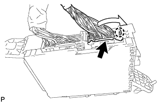
Engage the claw to connect the connector as shown in the illustration.
-
Install the instrument panel junction block assembly with the bolt and nut.
- Torque:
- Bolt
- 13 N*m { 127 kgf*cm, 9 ft.*lbf }
- Nut
- 8.0 N*m { 82 kgf*cm, 71 in.*lbf }
-
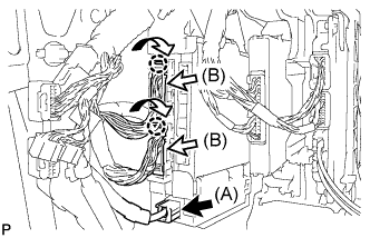
Connect the connector (A).
-
Engage the 2 claws to connect the 2 connectors (B) as shown in the illustration.
-
Connect the 3 connectors.
-
-
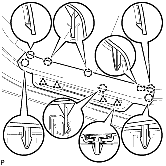
INSTALL NO. 3 INSTRUMENT PANEL STAY
-
Engage the 5 claws to install the 5 No. 3 instrument panel stays.
-
-
INSTALL INSTRUMENT PANEL SAFETY PAD ASSEMBLY
-
Engage the 5 claws and temporarily install the instrument panel safety pad assembly as shown in the illustration.
CAUTION:
Leaks of cold air may result in condensation in the instrument panel. This condensation may cause short circuits in electrical parts. Be sure to insert and fit the No. 1 heater to register duct and the No. 4 heater to register duct tightly to the No. 1 air duct sub-assembly.
Note
-
Do not damage the instrument panel safety pad assembly.
-
Do not allow the wire harnesses to interfere with the surrounding parts.
-
-
Install the 2 clips.
-
Install the 6 bolts <C> and nut <H> or <I>.
-
Install the 2 passenger airbag bolts <A> or <B>.
- Torque:
- 20 N*m { 204 kgf*cm, 15 ft.*lbf }
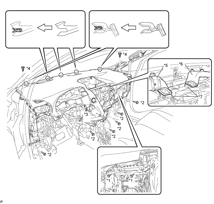
Text in Illustration *1 Passenger Airbag Bolt <A> or <B> *2 Bolt <C> *3 Nut <H> or <I> *4 Clip *5 No. 1 Heater To Register Duct *6 No. 4 Heater To Register Duct *7 No. 1 Air Duct Sub-assembly - - -
Engage the 2 claws to connect the room temperature sensor.
-
Engage each clamp.
-
Connect each connector.
-
-
CONNECT INSTRUMENT PANEL WIRE ASSEMBLY
-
Check that the power switch is off.
-
Check that the cable is disconnected from the negative (-) battery terminal.
CAUTION:
Wait at least 90 seconds after disconnecting the cable from the negative (-) battery terminal to disable the SRS system.
-
Connect the connector.
Note
When connecting any airbag connector, take care not to damage the airbag wire harness.
-
-
INSTALL NO. 1 CONSOLE BOX DUCT
-
Install the No. 1 console box duct with the screw <D>.
-
-
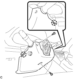
INSTALL SHIFT LEVER ASSEMBLY
Note
Check that the park/neutral position switch and the shift lever are in neutral.
-
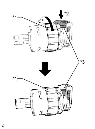
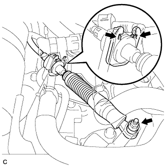
Text in Illustration *1 Lock Nut *2 Push in *3 Stopper Turn the lock nut of the transmission control cable counterclockwise. While holding the lock nut, push in the stopper.
-
Connect the outer part of the transmission control cable to the shift lever retainer.
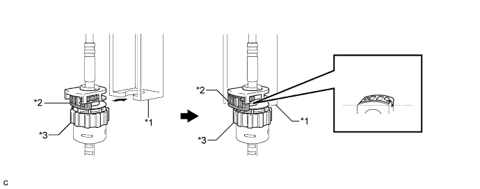
Text in Illustration *1 Shift Lever Retainer *2 Stopper *3 Lock Nut - - Note
The lock nut is fully seated against the shift lever retainer.
-
Install the transmission control cable end to the shift lever assembly.
Note
-
Install the floor shift cable with the uneven surface facing up.
-
Install the cable end all the way to the base of the pin.
-
-
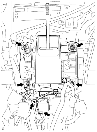
Install the shift lever assembly with the 4 nuts.
- Torque:
- 12 N*m { 122 kgf*cm, 9 ft.*lbf }
-
Connect the 3 clamps to the shift lever assembly.
-
Connect the 2 connectors.
-
-
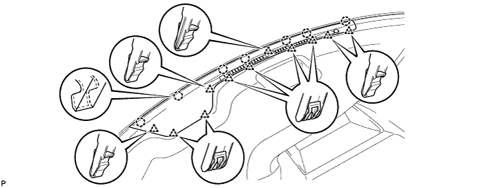
INSTALL NO. 1 DEFROSTER NOZZLE GARNISH
-
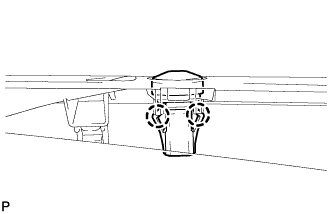
Engage the 2 claws to install the automatic light control sensor to the No. 1 defroster nozzle garnish.
-
Connect the connector.
-
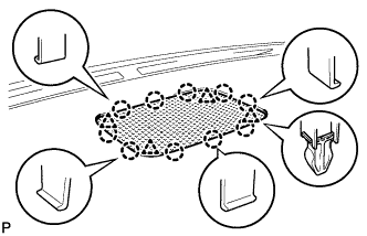
Engage the 7 claws and 11 clips to the No. 1 defroster nozzle garnish.
-
-
INSTALL FRONT NO. 4 SPEAKER ASSEMBLY
-
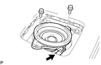
Connect the connector.
-
Install the front No. 4 speaker assembly with the 2 bolts.
- Torque:
- 7.5 N*m { 77 kgf*cm, 66 in.*lbf }
-
-
INSTALL NO. 1 SPEAKER OPENING COVER ASSEMBLY
-
Engage the 10 claws and 4 clips to install the No. 1 speaker opening cover assembly.
-
-
INSTALL NO. 1 INSTRUMENT PANEL REGISTER ASSEMBLY
-
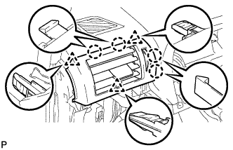
Engage the 4 claws and 3 clips to install the No. 1 instrument panel register assembly.
-
-
INSTALL NO. 2 INSTRUMENT PANEL REGISTER ASSEMBLY
Tech Tips
Use the same procedure for the No. 2 instrument panel register assembly and No. 1 instrument panel register assembly.
-
INSTALL FRONT PILLAR GARNISH LH
-
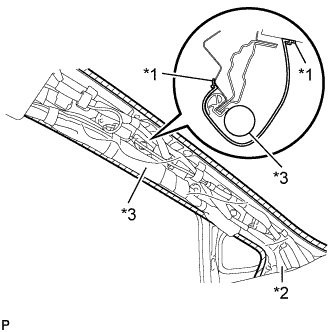
Text in Illustration *1 Adhesive Tape *2 Protective Cover *3 Curtain Shield Airbag Assembly Remove the protective cover.
-
Install a new clip <A> on the front pillar garnish LH.
-
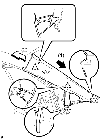
Engage the 2 guides and 2 clips, then install the front pillar garnish LH.
-
-
INSTALL INSTRUMENT SIDE PANEL LH
-
Engage the guide.
-
Engage the 2 clips.
-
Engage the claw to install the instrument side panel LH.
-
-
INSTALL FRONT PILLAR GARNISH RH
Tech Tips
Use the same procedure for the RH side and LH side Click here.
-
INSTALL INSTRUMENT SIDE PANEL RH
Tech Tips
Use the same procedure for the RH side and LH side Click here.
-
INSTALL GLOVE COMPARTMENT DOOR ASSEMBLY
-
Connect each connector.
-
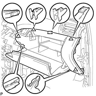
Engage the claw, 4 clips and guide.
-
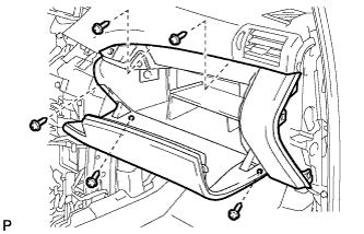
Install the glove compartment door assembly with the 5 screws <F>.
-
-
INSTALL FRONT PASSENGER SIDE KNEE AIRBAG ASSEMBLY
-
Check that the power switch is off.
-
Check that the cable is disconnected from the negative (-) battery terminal.
CAUTION:
Wait at least 90 seconds after disconnecting the cable from the negative (-) battery terminal to disable the SRS system.
-
Connect the airbag connector to the front passenger side knee airbag assembly.
Note
When connecting any airbag connector, take care not to damage the airbag wire harness.
-
Temporarily install the front passenger side knee airbag assembly with the claw and 2 pins.
-
Install the front passenger side knee airbag assembly with the 3 bolts.
- Torque:
- 10 N*m { 102 kgf*cm, 7 ft.*lbf }
Note
Confirm that the front passenger side knee airbag assembly is installed securely without any excessive gaps and is not protruding outward.
-
Text in Illustration *1 Protective Tape Remove the protective tape.
-
-
INSTALL INSTRUMENT PANEL GARNISH RH (w/o Airbag Cut Off Switch)
Tech Tips
Use the same procedure for the RH side and LH side.
-
INSTALL INSTRUMENT PANEL GARNISH RH (w/ Airbag Cut Off Switch)
-
Connect the connector.
-
Engage the 6 clips to install the instrument panel garnish RH.
-
-
INSTALL NO. 2 INSTRUMENT PANEL UNDER COVER SUB-ASSEMBLY
-
Connect the connector.
-
Engage the 2 guides and 4 claw to install the No. 2 instrument panel under cover sub-assembly.
-
-
INSTALL COWL SIDE TRIM SUB-ASSEMBLY RH
Tech Tips
Use the same procedure for the RH side and LH side Click here.
-
INSTALL FRONT DOOR SCUFF PLATE RH
Tech Tips
Use the same procedure for the RH side and LH side Click here.
-
INSTALL CONSOLE BOX (for LHD)
-
Text in Illustration *1 Clamp *2 Guide Engage the 3 guides as shown in the illustration.
-
Engage the 2 clamps.
-
Install the 3 clips.
-
Install the console box with the 5 screws <D>.
-
-
INSTALL CONSOLE BOX (for RHD)
-
Text in Illustration *1 Clamp *2 Guide Engage the 3 guides as shown in the illustration.
-
Engage the 2 clamps.
-
Install the 2 clips.
-
Install the console box with the 5 screws <D>.
-
-
INSTALL RADIO RECEIVER ASSEMBLY WITH REGISTER
-
Connect each connector.
-
Engage the 9 clips.
-
Install the radio receiver assembly with register with the 4 bolts.
- Torque:
- 4.9 N*m { 50 kgf*cm, 43 in.*lbf }
-
-
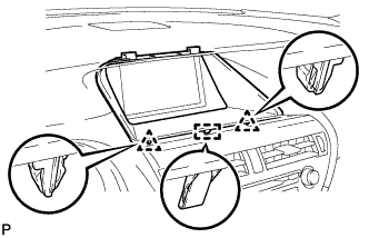
INSTALL LOWER INSTRUMENT PANEL FINISH PANEL
-
Engage the 7 clips to install the lower instrument panel finish panel as shown in the illustration.
-
-
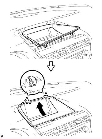
INSTALL INSTRUMENT PANEL FINISH PANEL
-
Engage the 2 guides, claw and 2 clips to install the instrument panel finish panel as shown in the illustration.
-
-
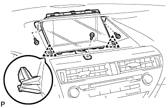
INSTALL MULTI-DISPLAY ASSEMBLY (w/ Navigation System)
-
Engage the 2 claws.
-
Install the multi-display assembly with the 3 bolts.
-
-
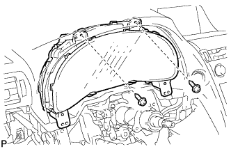
INSTALL ACCESSORY METER ASSEMBLY (w/o Navigation System)
-
Connect each connector.
-
Engage the 2 clips.
-
Install the accessory meter assembly with the 3 screws.
-
-
INSTALL CENTER INSTRUMENT CLUSTER FINISH PANEL
-
Engage the 2 clips as shown in the illustration.
-
Engage the 2 clips and guide to install the center instrument cluster finish panel.
-
-
INSTALL COMBINATION METER ASSEMBLY
-
Connect each connector.
-
Install the combination meter assembly with the 2 screws <G>.
-
-
INSTALL NO. 1 INSTRUMENT CLUSTER FINISH PANEL
-
Install the 2 screws <E>.
-
Install the No. 1 instrument cluster finish panel with the 2 clips.
-
-
INSTALL NO. 1 INSTRUMENT PANEL HOLE COVER
-
Engage the 2 claws to install the No. 1 instrument panel hole cover.
-
-
INSTALL NO. 2 INSTRUMENT PANEL HOLE COVER
Tech Tips
Use the same procedure for the No. 2 instrument panel hole cover and No. 1 instrument panel hole cover.
-
INSTALL STEERING POST ASSEMBLY
-
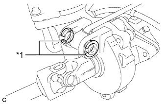
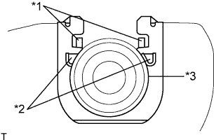
Text in Illustration *1 Bushing Check that the 2 bushings are securely installed to the steering column assembly.
Tech Tips
If the bushings are missing or damaged, replace the steering column assembly with a new one.
-
Install the steering post assembly with the bolt and 2 nuts.
- Torque:
- Bolt
- 36 N*m { 367 kgf*cm, 27 ft.*lbf }
- Nut
- 25 N*m { 255 kgf*cm, 18 ft.*lbf }
-
Engage the 2 wire harness clamps.
-
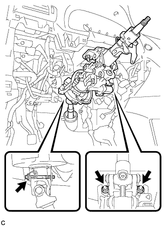
Connect the connectors and engage the wire harness clamps to the steering post assembly.
-
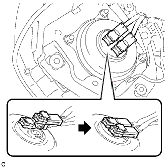
Connect the connector to the power steering ECU assembly.
Tech Tips
As shown in the illustration, securely return the lock lever to its original position to connect the connector.
-
Connect the connector to the power steering ECU assembly.
-
-
CONNECT STEERING INTERMEDIATE SHAFT ASSEMBLY
-
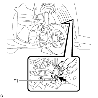
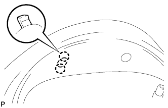
Text in Illustration *1 Matchmark Align the matchmarks on the steering intermediate shaft assembly and power steering link assembly.
-
Install the bolt.
- Torque:
- 35 N*m { 360 kgf*cm, 26 ft.*lbf }
-
Install the steering intermediate shaft assembly to the steering column hole shield.
-
Tighten the bolt.
-
-
INSTALL BRAKE PEDAL SUPPORT ASSEMBLY
for LHD Click here
for RHD Click here
-
CONNECT MASTER CYLINDER PUSH ROD CLEVIS
for LHD Click here
for RHD Click here
-
INSTALL BRAKE PEDAL RETURN SPRING
for LHD Click here
for RHD Click here
-
INSTALL BRAKE PEDAL STROKE SENSOR ASSEMBLY
for LHD Click here
for RHD Click here
-
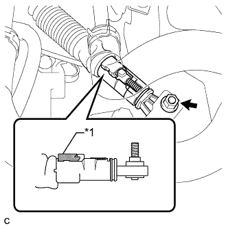
INSTALL STOP LIGHT SWITCH ASSEMBLY
-
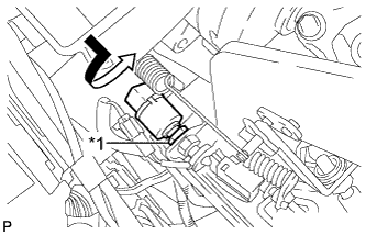
Text in Illustration *1 Lock Nut Temporarily install the stop light switch assembly with the stop light switch lock nut.
-
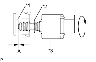
Text in Illustration *1 Cushion *2 Stop Light Switch Lock Nut *3 Stop Light Switch Turn the stop light switch assembly so that the clearance between the nut end and stop light switch cushion is between A.
Standard Clearance Area Measurement A 0.5 to 2.4 mm (0.0197 to 0.0945 in.) -
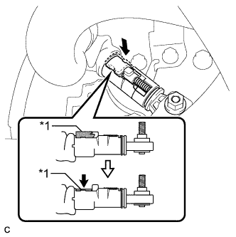
Tighten the stop light switch lock nut.
- Torque:
- 17 N*m { 170 kgf*cm, 12 ft.*lbf }
-
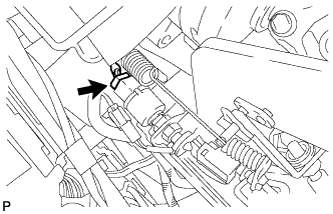
Connect the connector.
-
-
INSPECT AND ADJUST BRAKE PEDAL
for LHD Click here
for RHD Click here
-
ADJUST BRAKE PEDAL STROKE SENSOR ASSEMBLY
for LHD Click here
for RHD Click here
-
INSTALL NO. 4 AIR DUCT SUB-ASSEMBLY (for LHD)
-
Engage the guide and claw to install the No. 4 air duct sub-assembly.
Note
Do not damage the claw or guide.
-
-
INSTALL NO. 4 AIR DUCT SUB-ASSEMBLY (for RHD)
-
Engage the guide and claw to install the No. 4 air duct sub-assembly.
Note
Do not damage the claw or guide.
-
-
INSTALL DRIVER SIDE KNEE AIRBAG ASSEMBLY
-
Check that the power switch is off.
-
Check that the cable is disconnected from the negative (-) battery terminal.
CAUTION:
Wait at least 90 seconds after disconnecting the cable from the negative (-) battery terminal to disable the SRS system.
-
Engage the claw to connect the hood lock control cable to the driver side knee airbag assembly.
-
Connect the airbag connector to the driver side knee airbag assembly.
Note
When connecting any airbag connector, take care not to damage the airbag wire harness.
-
Temporarily install the driver side knee airbag assembly with the 2 claws and 2 hooks.
-
Install the driver side knee airbag assembly with the 4 bolts.
- Torque:
- 10 N*m { 102 kgf*cm, 7 ft.*lbf }
Note
Confirm that the driver side knee airbag assembly is installed securely without any excessive gaps and is not protruding outward.
-
-
INSTALL LOWER INSTRUMENT PANEL FINISH PANEL SUB-ASSEMBLY
-
Connect each connector.
-

Engage the 8 clips and 2 guides.
-
Install the lower instrument panel finish panel sub-assembly with the 2 screws <D>.
-
Engage the 2 claws to close the cover as shown in the illustration.
-
-
INSTALL NO. 1 SWITCH HOLE BASE
-
Connect each connector.
-
Engage the 4 claws and 2 guides to install the No. 1 switch hole base.
-
-
INSTALL INSTRUMENT PANEL GARNISH LH
-
Engage the 6 clips to install the instrument panel garnish LH.
-
-
INSTALL NO. 1 INSTRUMENT PANEL UNDER COVER SUB-ASSEMBLY (for LHD)
-
Engage each clamp.
-
Connect each connector.
-
Engage the claw and 2 guides.
-

Install the No. 1 instrument panel under cover sub- assembly with the 2 screws <D>.
-
-
INSTALL NO. 1 INSTRUMENT PANEL UNDER COVER SUB-ASSEMBLY (for RHD)
-
Engage each clamp.
-
Connect each connector.
-
Engage the claw and 2 guides.
-
Install the No. 1 instrument panel under cover sub- assembly with the 2 screws <D>.
-
-
INSTALL COWL SIDE TRIM SUB-ASSEMBLY LH
-
Engage the 2 clips to install the cowl side trim sub-assembly LH.
-
Install the clip.
-
-
INSTALL FRONT DOOR SCUFF PLATE LH
-
w/ Illumination:
-
Connect the connector.
-
-
Engage the 4 clips, guide and 7 claws, and install the front door scuff plate LH.
-
-
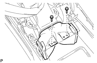
INSTALL REAR CONSOLE BOX ASSEMBLY
-
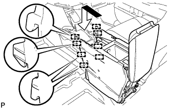
Engage the 8 guides as shown in the illustration.
-
Text in Illustration *1 Screw *2 Bolt Install the rear console box assembly with the 2 screws and 4 bolts.
-
Connect each connector.
-
-
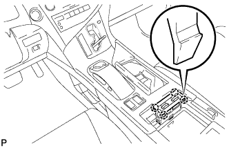
INSTALL MULTI-MEDIA INTERFACE ECU ASSEMBLY
-
Connect the connector.
-
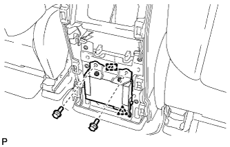
Engage the clip and guide.
-
Install the multi-media interface ECU assembly with the 2 bolts.
- Torque:
- 6.0 N*m { 61 kgf*cm, 53 in.*lbf }
-
-
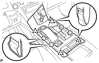
INSTALL CONSOLE REAR END PANEL SUB-ASSEMBLY
-
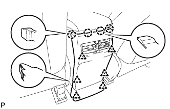
w/o Rear Seat Entertainment System:
-
Engage the 4 claws and 6 clips to install the console rear end panel sub-assembly.
-
-
w/ Rear Seat Entertainment System:
-
Connect each connector.
-
Engage the 4 claws and 6 clips to install the console rear end panel sub-assembly.
-
-
-
INSTALL NO. 2 CONSOLE BOX DUCT
-
Install the No. 2 console box duct with the 2 screws.
-
-
INSTALL UPPER CONSOLE PANEL SUB-ASSEMBLY
-
Engage the clamp.
-
Connect each connector.
-
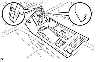
Engage the 3 claws and 3 clips.
-
w/o Seat Heater System:
-
Connect the connector to the console box hole cover.
-
-
w/ Seat Heater System:
-
Engage the 4 claws to install the seat heater switch assembly.
-
Connect the connector.
-
-
Engage the 4 claws and 4 clips to install the upper console panel sub-assembly.
-
-
INSTALL SHIFT LEVER KNOB SUB-ASSEMBLY
-
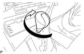
Turn the shift lever knob sub-assembly clockwise to install the shift lever knob sub-assembly.
-
-
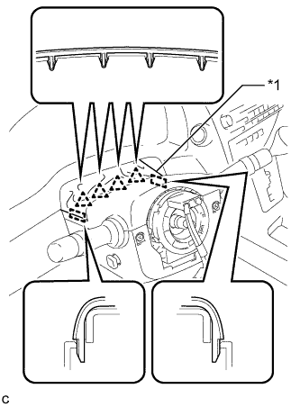
INSTALL TURN SIGNAL SWITCH ASSEMBLY WITH SPIRAL CABLE SUB-ASSEMBLY
-
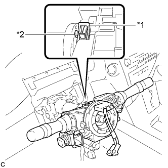
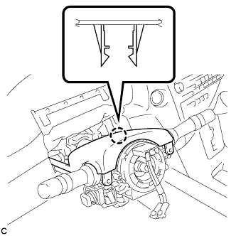
Text in Illustration *1 Clamp *2 Claw Using pliers, expand the clamp.
-
While holding the clamp expanded, install the turn signal switch assembly with spiral cable sub-assembly to the steering column assembly and engage the claw.
-
Return the clamp to its original position.
-
Connect the connectors to the turn signal switch assembly with spiral cable sub-assembly.
-
-
INSTALL STEERING COLUMN COVER
-
Engage the claw to install the upper steering column cover.
-
Engage the 2 claws to install the lower steering column cover to the upper steering column cover.
Note
Do not damage the tilt and telescopic switch.
-
Install the 3 screws.
- Torque:
- 2.0 N*m { 20 kgf*cm, 18 in.*lbf }
-
Text in Illustration *1 Instrument Panel Cluster Finish Panel Engage the 4 clips and 2 guides to install the instrument panel cluster finish panel to the upper steering column cover.
-
-
ADJUST SPIRAL CABLE
-
Check that the power switch is off.
-
Check that the cable is disconnected from the negative (-) battery terminal.
CAUTION:
Wait at least 90 seconds after disconnecting the cable from the negative (-) battery terminal to disable the SRS system.
-
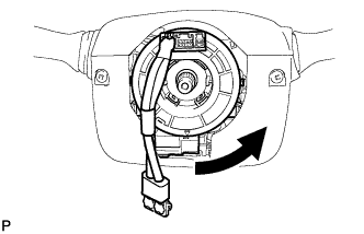
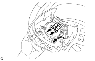
Rotate the spiral cable counterclockwise slowly by hand until it stops.
Note
Do not turn the spiral cable using the airbag wire harness.
-
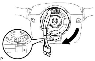
Text in Illustration *1 Alignment Mark Rotate the spiral cable clockwise approximately 2.5 turns to align the marks.
Note
Do not turn the spiral cable using the airbag wire harness.
Tech Tips
The spiral cable will rotate approximately 2.5 turns to both the left and right from the center.
-
-
INSTALL STEERING WHEEL ASSEMBLY
-
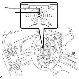
Text in Illustration *1 Matchmark Align the matchmarks on the steering wheel assembly and steering main shaft.
-
Install the steering wheel assembly set nut.
- Torque:
- 50 N*m { 510 kgf*cm, 37 ft.*lbf }
-
Connect the connectors to the spiral cable sub-assembly.
-
-
INSPECT STEERING WHEEL CENTER POINT
-
INSTALL STEERING PAD
-
Check that the power switch is off.
-
Check that the cable is disconnected from the negative (-) battery terminal.
CAUTION:
Wait at least 90 seconds after disconnecting the cable from the negative (-) battery terminal to disable the SRS system.
-
Connect the airbag connectors to the steering pad.
Note
-
When connecting any airbag connector, take care not to damage the airbag wire harness.
-
Be sure to only connect the connectors to each corresponding color.
-
-
Push in the lock to install the airbag connector.
-
Connect the horn connector to the steering pad.
-
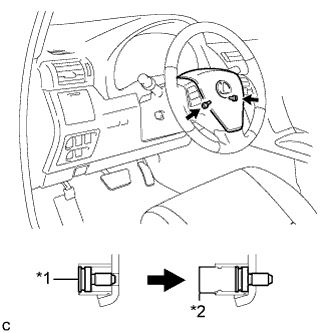
Text in Illustration *1 "TORX" Screw *2 Screw Case Confirm that the circumference groove of each "TORX" screw fits in the screw case, and place the steering pad onto the steering wheel assembly.
-
Using a T30 "TORX" socket wrench, tighten the 2 "TORX" screws.
- Torque:
- 8.8 N*m { 90 kgf*cm, 78 in.*lbf }
-
-
INSTALL LOWER NO. 3 STEERING WHEEL COVER
-
Engage the claw to install the lower No. 3 steering wheel cover.
-
-
INSTALL LOWER NO. 2 STEERING WHEEL COVER
-
Engage the claw to install the lower No. 2 steering wheel cover.
-
-
CONNECT INLET HEATER WATER HOSE
-
Using pliers, grip the claws of the clip and slide the clip to connect the inlet heater water hose.
-
-
CONNECT OUTLET HEATER WATER HOSE
-
Using pliers, grip the claws of the clip and slide the clip to connect the outlet heater water hose.
-
-
CONNECT AIR CONDITIONING TUBE AND ACCESSORY ASSEMBLY
-
Remove the attached vinyl tape from the pipe.
-
Sufficiently apply compressor oil to a new O-ring and the fitting surface of the air conditioning tube and accessory assembly.
Compressor oil ND-OIL 11 or equivalent -
Install the O-ring on the air conditioning tube and accessory assembly.
Note
-
Keep the O-ring and O-ring fitting surfaces clean from dirt or any foreign objects.
-
Do not use any compressor oil other than ND-OIL 11 or equivalent. If any compressor oil other than ND-OIL 11 or equivalent is used, compressor motor insulation performance may decrease, resulting in a leakage of electric power.
-
-
Install the air conditioning tube and accessory assembly.
-
-
CONNECT SUCTION PIPE SUB-ASSEMBLY
-
Remove the attached vinyl tape from the pipe.
-
Sufficiently apply compressor oil to a new O-ring and the fitting surface of the suction pipe sub-assembly.
Compressor oil ND-OIL 11 or equivalent -
Install the O-ring on the suction pipe sub-assembly.
Note
-
Keep the O-ring and O-ring fitting surfaces clean from dirt or any foreign objects.
-
Do not use any compressor oil other than ND-OIL 11 or equivalent. If any compressor oil other than ND-OIL 11 or equivalent is used, compressor motor insulation performance may decrease, resulting in a leakage of electric power.
-
-
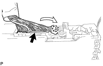
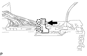
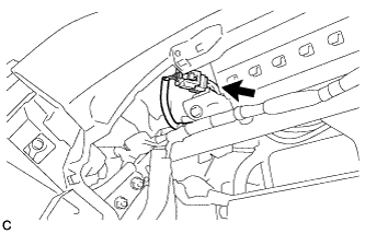
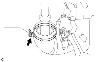
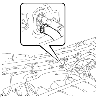
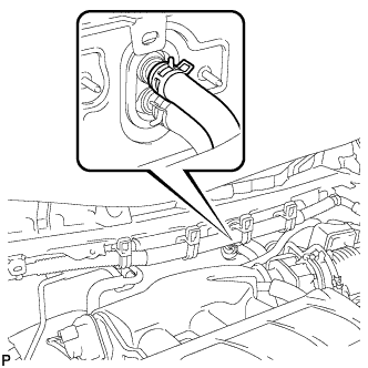
Install the suction pipe sub-assembly.
-
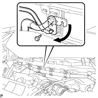
Move the hook connector in the direction indicated by the arrow in the illustration.
-
Insert the pipe joint into the fitting hole securely and tighten the bolt.
- Torque:
- 9.8 N*m { 100 kgf*cm, 87 in.*lbf }
-
Engage the 6 clamps to the engine wire harness.
-
-
INSTALL OUTER COWL TOP PANEL SUB-ASSEMBLY
for LHD Click here
for RHD Click here
-
INSTALL FRONT SHOCK ABSORBER CAP LH (w/ Air Suspension)
-
Install the front shock absorber cap with the 3 nuts.
- Torque:
- 14 N*m { 143 kgf*cm, 10 ft.*lbf }
-
-
INSTALL FRONT SHOCK ABSORBER CAP RH (w/ Air Suspension)
Tech Tips
Use the same procedure for the RH side and LH side.
-
INSTALL WINDSHIELD WIPER MOTOR AND LINK ASSEMBLY
-
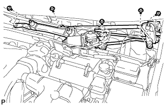
Install the windshield wiper motor and link assembly with the 5 bolts.
- Torque:
- 7.0 N*m { 71 kgf*cm, 62 in.*lbf }
Note
Be careful not to damage the windshield when installing the windshield wiper motor and link assembly.
-
w/o Deicer:
-
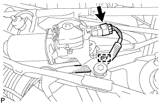
Engage the clamp.
-
Connect the connector.
-
-
w/ Deicer:
-
Engage the clamp.
-
Connect each connector.
-
-
-
INSTALL COWL TOP VENTILATOR LOUVER SUB-ASSEMBLY
-
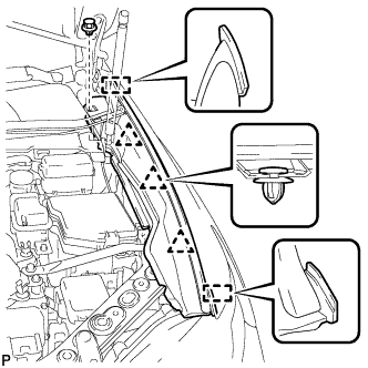
Engage the 10 guides.
-
Engage the 6 claws and guide <A> as shown in the illustration.
-
Install the 2 clips to cowl top ventilator louver sub-assembly.
-
-
INSTALL FRONT WIPER ARM AND BLADE ASSEMBLY RH
-
Operate the wiper and stop the windshield wiper motor at the automatic stop position.
-
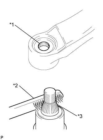
Text in Illustration *1 Wiper Arm Serration *2 Wire Brush *3 Wiper Pivot Serration When reusing the front wiper arm and blade assembly RH:
-
Clean the wiper arm serrations.
-
-
When reusing the windshield wiper link assembly:
-
Clean the wiper pivot serrations with a wire brush.
-
-
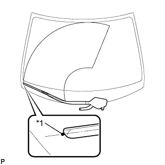
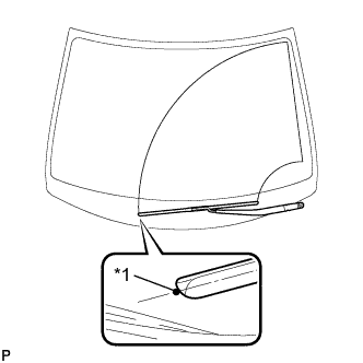
Text in Illustration *1 Ceramic Dot Install the front wiper arm and blade assembly RH with the 2 nuts to the position shown in the illustration.
- Torque:
- 24 N*m { 245 kgf*cm, 18 ft.*lbf }
Tech Tips
While holding the tip of the wiper blade on the glass at approximately 20 mm above the ceramic dot, press down on the wiper arm and tighten the nut. Then raise and lower the wiper arm a few times to confirm that it has settled to the specified position.
-
-
INSTALL FRONT WIPER ARM AND BLADE ASSEMBLY LH
-

Text in Illustration *1 Wiper Arm Serration *2 Wire Brush *3 Wiper Pivot Serration When reusing the front wiper arm and blade assembly LH:
-
Clean the wiper arm serrations.
-
-
When reusing the windshield wiper link assembly:
-
Clean the wiper pivot serrations with a wire brush.
-
-
Text in Illustration *1 Ceramic Dot Install the front wiper arm and blade assembly LH with the nut to the position shown in the illustration.
- Torque:
- 24 N*m { 245 kgf*cm, 18 ft.*lbf }
Tech Tips
Hold the wiper arm by hand while tightening the nut.
-
Operate the front wipers while spraying washer fluid on the windshield glass. Make sure that the front wipers function properly and there is no interference with the vehicle body.
-
-
INSTALL FRONT WIPER ARM HEAD CAP
-
Engage the 3 claws to install the front wiper arm head cap.
-
-
INSTALL FRONT FENDER TO COWL SIDE SEAL LH
-
Wipe off any tape adhesive residue with cleaner.
-
Text in Illustration *1 Double-sided Tape Engage the 2 claws and install a new front fender to cowl side seal LH.
-
-
INSTALL FRONT FENDER TO COWL SIDE SEAL RH
Tech Tips
Use the same procedure for the RH side and LH side.
-
INSTALL FRONT FENDER TOP REINFORCEMENT SUB-ASSEMBLY LH
-
Engage the 3 clips and 2 guides.
-
Install the front fender top reinforcement sub-assembly LH with the clip.
-
Text in Illustration *1 Hood to Cowl Top Seal Engage the clip to the hood to cowl top seal to the front fender top reinforcement sub-assembly LH.
-
-
INSTALL FRONT FENDER TOP REINFORCEMENT SUB-ASSEMBLY RH
Tech Tips
Use the same procedure for the RH side and LH side.
-
INSTALL FRONT SEAT ASSEMBLY
-
for LH Side:
-
Refer to the procedure from Install Front Seat Assembly Click here.
-
-
for RH Side:
Tech Tips
Use the same procedure for the RH side and LH side.
-
-
CONNECT CABLE TO NEGATIVE BATTERY TERMINAL
Note
-
Make sure that the cable has been disconnected from the negative (-) battery terminal for at least 2 seconds before reconnecting the cable.
-
Reset the auto tilt away function setting to the previous condition by changing the customize parameter Click here.
-
When disconnecting the cable, some systems need to be initialized after the cable is reconnected Click here.
-
-
INSTALL REAR DECK FLOOR BOX
-

Install the rear deck floor box with the 3 clips.
-
-
INSTALL FRONT WHEEL LH
- Torque:
- 103 N*m { 1050 kgf*cm, 76 ft.*lbf }
-
ALIGN FRONT WHEELS FACING STRAIGHT AHEAD
-
ADD COOLANT (for Engine)
-
Tighten the radiator drain cock plug by hand.
-
Tighten the 2 cylinder block drain cock plugs.
- Torque:
- 13 N*m { 130 kgf*cm, 9 ft.*lbf }
-
Loosen the air drain cock plug on the water inlet housing.
-
Add TOYOTA Super Long Life Coolant (SLLC) to the radiator inlet opening until coolant overflows from the air drain cock hole. Then tighten the air drain cock plug to the water inlet housing.
- Torque:
- 13 N*m { 130 kgf*cm, 9 ft.*lbf }
-
Slowly fill the radiator with TOYOTA Super Long Life Coolant (SLLC).
Standard Capacity Item Capacity Engine coolant 11.7 liters (12.4 US qts, 10.2 lmp. qts) Tech Tips
-
TOYOTA vehicles are filled with TOYOTA SLLC at the factory. In order to avoid damage to the engine cooling system and other technical problems, only use TOYOTA SLLC or similar high quality ethylene glycol based non-silicate, non-amine, non-nitrite, non-borate coolant with long-life hybrid organic acid technology (coolant with long-life hybrid organic acid technology is a combination of low phosphates and organic acids).
-
Contact your TOYOTA dealer for further details.
Note
Never use water as a substitute for engine coolant.
-
-
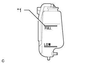
Text in Illustration *1 Full Line Slowly pour coolant into the radiator reservoir tank until it reaches the full line.
-
Install the radiator cap.
-
Squeeze the No. 1 and No. 2 radiator hoses several times by hand, and then check the level of the coolant.
If the coolant level is low, add coolant.
-
Bleed air from the cooling system.
-
Put the engine in inspection mode Click here.
-
Warm up the engine until the thermostat opens. While the thermostat is open, circulate the coolant for several minutes.
Tech Tips
The thermostat open timing can be confirmed by squeezing the No. 2 radiator hose by hand, and checking when the engine coolant starts to flow inside the hose.
-
Maintain the engine speed at 2500 rpm.
-
Squeeze the inlet and No. 1 and No. 2 radiator hoses several times by hand to bleed air.
CAUTION:
When squeezing the radiator hoses:
-
Wear protective gloves.
-
Be careful as the radiator hoses are hot.
-
Keep your hands away from the cooling fans.
Note
-
Make sure that the radiator reservoir still has some coolant in it.
-
If the coolant temperature gauge indicates an excessive temperature, turn off the engine and let it cool.
-
If there is not enough coolant, the engine may overheat or be seriously damaged.
-
If the radiator reservoir does not have enough coolant, perform the following: 1) stop the engine, 2) wait until the coolant has cooled down, and 3) add coolant until the reservoir is filled to the Full line.
-
-
-
Stop the engine and wait until the engine coolant cools down.
-
Add engine coolant to the full line on the radiator reservoir.
-
-
CHARGE WITH REFRIGERANT
-
Perform vacuum purging using a vacuum pump.
-
Charge with refrigerant HFC-134a (R134a).
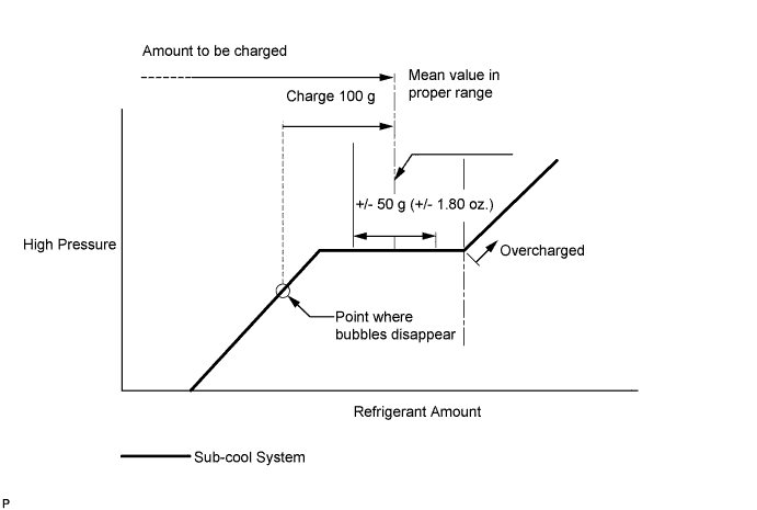
Standard 550 to 650 g (19.4 to 22.9 oz.) - SST
- 09985-20010 ( 09985-02010, 09985-02050, 09985-02060, 09985-02070, 09985-02080, 09985-02090, 09985-02110, 09985-02130, 09985-02140, 09985-02150 )
Note
-
Do not turn the A/C on before charging with refrigerant. Doing so will cause the compressor to work without refrigerant, resulting in overheating of the cooler compressor.
-
Approximately 100 g (3.53 oz.) of refrigerant may need to be charged after bubbles disappear. The refrigerant amount should be checked by quantity, not with the sight glass.
-
Avoid using the gauge manifold set that had been used for vehicles with conventional compressor oil (ND-OIL 8 or equivalent) as much as possible. This will cause compressor oil remaining in the manifold to enter the vehicle, resulting in insulation performance deterioration. A gauge manifold set that had been used 3 times or less can be reused if an appropriate one is not available.
Tech Tips
Ensure that sufficient refrigerant is available to recharge the system when using a refrigerant recovery unit. Refrigerant recovery units are not always able to recover 100% of the refrigerant from an A/C system.
-
-
WARM UP COMPRESSOR
-
Keep the A/C switch on for at least 2 minutes to warm up the compressor.
Note
Be sure to warm up the compressor when turning the A/C on after removing and installing the cooler refrigerant lines (including the compressor), to prevent damage to the compressor.
-
-
INSPECT FOR REFRIGERANT LEAK
-
After recharging with refrigerant, inspect for refrigerant leaks using a halogen leak detector.
-
Carry out the test under the following conditions:
-
Turn the power switch off.
-
Secure good ventilation (the halogen leak detector may react to volatile gases which are not refrigerant, such as evaporated gasoline and exhaust gas).
-
Repeat the test 2 or 3 times.
-
Make sure that there is some refrigerant remaining in the refrigeration system.
When the compressor is off: approx. 392 to 588 kPa (4 to 6 kgf/cm2, 57 to 85 psi)
-
-
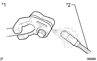
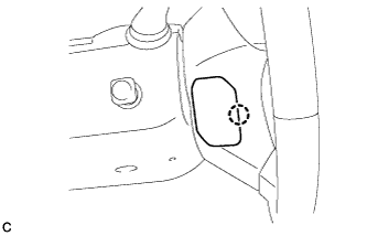
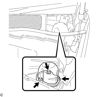
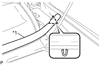
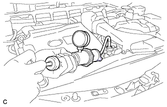
Text in Illustration *1 Inspect for Leak *2 Halogen Leak Detector Using a halogen leak detector, inspect for refrigerant leaks from the refrigerant lines.
-
Text in Illustration *1 Halogen Leak Detector *2 Drain Hose Bring the halogen leak detector close to the drain hose with the detector's power off, and then turn the detector on.
Tech Tips
-
After the blower motor has stopped, let the cooling unit stand for more than 15 minutes.
-
Bring the halogen leak detector sensor under the drain hose.
-
When bringing the halogen leak detector close to the drain hose, make sure that the halogen leak detector does not react to volatile gases. If it is not possible to avoid interference from volatile gases, the vehicle should be lifted up to allow testing.
-
-
If a refrigerant leak is not detected from the drain hose, remove the blower motor control from the cooling unit. Insert the halogen leak detector sensor into the unit and perform the test.
-
Disconnect the pressure switch connector and leave it for approximately 20 minutes. Bring the halogen leak detector close to the pressure switch and perform the test.
-
-
INSPECT FOR COOLANT LEAK (for Engine)
CAUTION:
Do not remove the radiator cap while the engine and radiator are still hot. Pressurized hot engine coolant and steam may be released and cause serious burns.
Note
Before performing each inspection, turn the A/C switch off.
-
Remove the radiator cap.
-
Fill the radiator with coolant and attach a radiator cap tester.
-
Put the engine in inspection mode Click here.
-
Warm up the engine.
-
Using the radiator cap tester, increase the pressure inside the radiator to 118 kPa (1.2 kgf/cm2, 17 psi), and check that the pressure does not drop.
If the pressure drops, check the hoses, radiator, exhaust center pipe assembly and the heater hose around the water temperature switch and engine water pump for leaks. If no external leaks are found, check the heater core, cylinder block and cylinder head.
-
Remove the radiator cap tester.
-
Install the radiator cap.
-
-
INSTALL COOL AIR INTAKE DUCT SEAL
-
Install the cool air intake duct seal with the 6 clips.
-
-
INSTALL ENGINE ROOM SIDE COVER
-
Install the engine room side cover with the 4 clips.
-
-
INSTALL ENGINE ROOM SIDE COVER LH
-
Engage the guide.
-
Install the engine room side cover LH with the 4 clips.
-
-
INSPECT SHIFT LEVER POSITION
-
When moving the shift lever from P to R with the power switch on (IG) and the brake pedal depressed, make sure that the shift lever moves smoothly and correctly into position.
-
Turn the power switch on (READY) and make sure that the vehicle moves forward when moving the shift lever from N to D and moves rearward when moving the shift lever to R.
If the operation cannot be performed as specified, inspect the shift lever position sensor and check the shift lever assembly installation condition.
-
-
ADJUST SHIFT LEVER POSITION
-
Apply the parking brake and move the shift lever to N.
Note
Check that the control shaft lever and the shift lever are in neutral.
-
Remove the No. 1 engine under cover.
-
Remove the nut from the control shaft lever.
-
Using a screwdriver, disengage the 4 claws and disconnect the control cable with clip from the control cable bracket.
-
Remove the clip.
-
Turn back the boot.
-
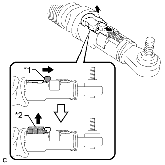
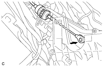
Text in Illustration *1 Slider *2 Lock Piece Slide the slider of the transmission control cable in the direction indicated by the arrow and pull the lock piece outward.
-
Install a new clip to the control cable bracket.
-
Text in Illustration *1 Claw A *2 Claw B *3 Control Cable Install the control cable to the control cable bracket.
Note
-
Make sure that the claws A on the clip are securely fit into the bracket holes.
-
Make sure that the cable is securely installed inside of the claws B of the clip.
-
-
Text in Illustration *1 Lock Piece Connect the transmission control cable to the control shaft lever with the nut.
- Torque:
- 12 N*m { 122 kgf*cm, 9 ft.*lbf }
Note
Check that the lock piece is pulled up.
-
Text in Illustration *1 Lock Piece Push the lock piece into the adjuster case.
Note
-
Check that the shift lever position sensor and the shift lever are in neutral.
-
Securely push in the lock piece until the slider lock is engaged.
-
-
Refit the boot.
-
After adjusting the shift lever position, check the operation and function of the shift lever. If there is a problem, adjust the position again.
-
Install the No. 1 engine under cover.
-
-
INSPECT SHIFT LEVER OPERATION
-
While moving the shift lever from N to each position, check that the lever moves smoothly and that the shift position indicator comes on properly according to the shift lever position.
-
Turn the power switch on (READY) and check the following:
-
When the shift lever is moved to D, the vehicle moves forward.
-
When the shift lever is moved to R, the vehicle moves in reverse.
Note
The vehicle should not move when the shift position indicator is off.
-
-
-
INSPECT STEERING PAD
-
Visually check for defects with the steering pad installed on the vehicle.
-
The defects are as follows:
-
Cuts on the surface and in the grooves of the steering pad
-
Small cracks on the surface and in the grooves of the steering pad
-
Significant discoloration on the surface and in the grooves of the steering pad
OK No defects are found. Tech Tips
If any of the defects is found, replace the steering pad with a new one.
-
-
-
Make sure that the horn sounds.
Tech Tips
If the horn does not sound, inspect the horn system Click here.
-
-
INSPECT SUSPENSION CONTROL SYSTEM (w/ Air Suspension)
-
Inspect the suspension control system Click here.
-
-
INSPECT SRS WARNING LIGHT
-
Inspect the SRS warning light Click here.
-
-
INITIALIZE SERVO MOTOR
-
Turn the power switch off.
-
Connect the intelligent tester to the DLC3.
-
Turn the power switch on (IG).
-
Press the A/C OFF switch.
-
Turn the intelligent tester on.
-
Enter the following menus: Body / Air Conditioner / Utility / Servomotor Initialization.
-
According to the intelligent tester display, select the "Next" switch.
-
According to the intelligent tester display, select the "Next" switch.
Tech Tips
During initialization, the AUTO indicator illuminates. When initialization is complete, the indicator turns off.
-
According to the intelligent tester display, select the exit to finish the initialization.
-