ROOM TEMPERATURE SENSOR INSTALLATION

-
INSTALL ROOM TEMPERATURE SENSOR
-
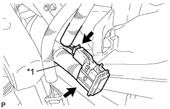
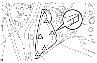
Text in Illustration *1 Aspirator Pipe Connect the connector and aspirator pipe.
-
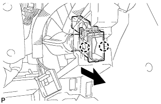
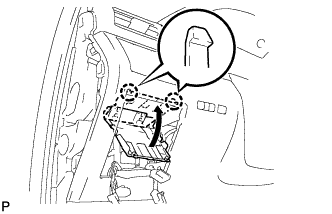
Engage the 2 claws to install the room temperature sensor as shown in the illustration.
-
-
INSTALL LOWER INSTRUMENT PANEL FINISH PANEL SUB-ASSEMBLY
-
Connect each connector.
-

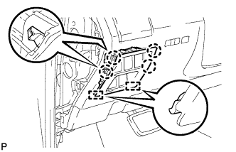
Engage the 8 clips and 2 guides.
-
Install the lower instrument panel finish panel sub-assembly with the 2 screws <D>.
-
Engage the 2 claws to close the cover as shown in the illustration.
-
-
INSTALL NO. 1 SWITCH HOLE BASE
-
Connect each connector.
-
Engage the 4 claws and 2 guides to install the No. 1 switch hole base.
-
-
INSTALL INSTRUMENT PANEL GARNISH LH
-
Engage the 6 clips to install the instrument panel garnish LH.
-
-
CONNECT CABLE TO NEGATIVE BATTERY TERMINAL (w/ Air Suspension)
Note
When disconnecting the cable, some systems need to be initialized after the cable is reconnected Click here.
-
INSTALL REAR DECK FLOOR BOX (w/ Air Suspension)
-

Install the rear deck floor box with the 3 clips.
-
-
INSPECT SUSPENSION CONTROL SYSTEM (w/ Air Suspension)
-
Inspect the suspension control system Click here.
-