ROOM TEMPERATURE SENSOR INSPECTION

-
INSPECT ROOM TEMPERATURE SENSOR
-
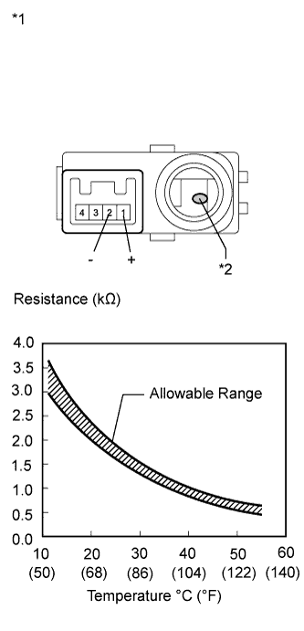
Text in Illustration *1 Component without harness connected
(Room Temperature Sensor)
*2 Sensing Portion Measure the resistance according to the value(s) in the table below.
Standard Resistance Tester Connection Condition Specified Condition 1 (+) - 2 (-) 10°C (50°F) 3.00 to 3.73 kΩ 1 (+) - 2 (-) 15°C (59°F) 2.45 to 2.88 kΩ 1 (+) - 2 (-) 20°C (68°F) 1.95 to 2.30 kΩ 1 (+) - 2 (-) 25°C (77°F) 1.60 to 1.80 kΩ 1 (+) - 2 (-) 30°C (86°F) 1.28 to 1.47 kΩ 1 (+) - 2 (-) 35°C (95°F) 1.00 to 1.22 kΩ 1 (+) - 2 (-) 40°C (104°F) 0.80 to 1.00 kΩ 1 (+) - 2 (-) 45°C (113°F) 0.65 to 0.85 kΩ 1 (+) - 2 (-) 50°C (122°F) 0.50 to 0.70 kΩ 1 (+) - 2 (-) 55°C (131°F) 0.44 to 0.60 kΩ 1 (+) - 2 (-) 60°C (140°F) 0.36 to 0.50 kΩ Note
-
Hold the sensor only by its connector. Touching the sensor may change the resistance value.
-
When measuring, the sensor temperature must be the same as the ambient temperature.
Tech Tips
As the temperature increases, the resistance decreases (see the graph).
If the resistance is not as specified, replace the room temperature sensor.
-
-
-
INSPECT ROOM HUMIDITY SENSOR
-
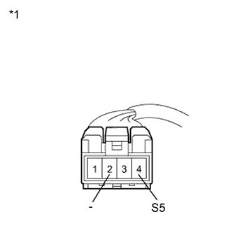
Text in Illustration *1 Front view of wire harness connector
(to Room Humidity Sensor)
Disconnect the room humidity sensor connector.
-
Measure the voltage according to the value(s) in the table below.
Standard Voltage Tester Connection Condition Specified Condition 4 (S5) - 2 (-) Power switch on (IG) 4.5 to 5.5 V If the voltage is not as specified, repair or replace the wire harness or connector.
-
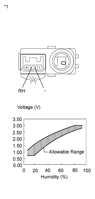
Text in Illustration *1 Component with harness connected
(Room Humidity Sensor)
Reconnect the room humidity sensor connector.
-
Turn the power switch on (IG).
-
Measure the voltage according to the value(s) in the table below.
Standard Voltage Tester Connection Condition Specified Condition 3 (RH) - 2 (-) at 25°C (77°F)
Humidity 10%
0.7 to 1.08 V 3 (RH) - 2 (-) at 25°C (77°F)
Humidity 20%
0.72 to 1.57 V 3 (RH) - 2 (-) at 25°C (77°F)
Humidity 30%
1.13 to 1.95 V 3 (RH) - 2 (-) at 25°C (77°F)
Humidity 40%
1.61 to 2.24 V 3 (RH) - 2 (-) at 25°C (77°F)
Humidity 50%
1.99 to 2.46 V 3 (RH) - 2 (-) at 25°C (77°F)
Humidity 60%
2.26 to 2.66 V 3 (RH) - 2 (-) at 25°C (77°F)
Humidity 70%
2.48 to 2.85 V 3 (RH) - 2 (-) at 25°C (77°F)
Humidity 80%
2.68 to 3.04 V 3 (RH) - 2 (-) at 25°C (77°F)
Humidity 90%
2.87 to 3.05 V Note
-
Do not touch the room humidity sensor because it may be affected by body temperature and may not work properly.
-
Hold the sensor only by its connector.
-
The output voltage at the ambient temperature 25°C (77°F) is shown above.
Tech Tips
As the humidity increases, the voltage increases (see the graph).
If the voltage is not as specified, replace the room humidity sensor.
-
-