AIR CONDITIONING SYSTEM IG Power Source Circuit
DESCRIPTION
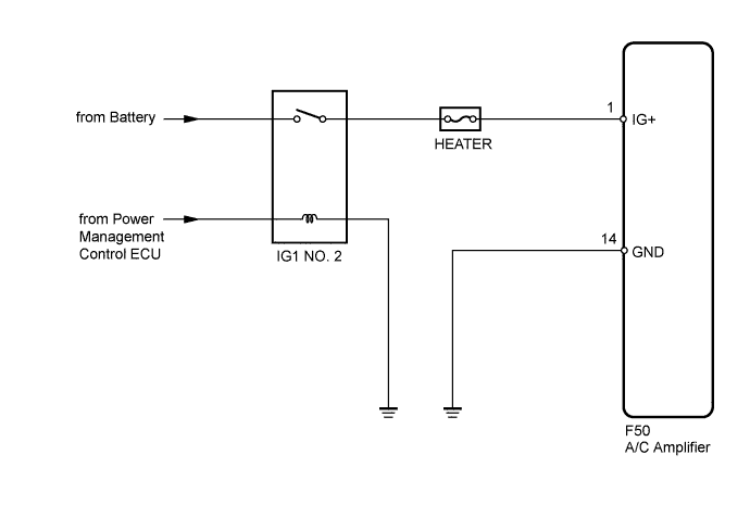
The main power source is supplied to the A/C amplifier when the power switch is turned on (IG).
The power source is used for operating the A/C amplifier and servo motor, etc.
WIRING DIAGRAM
INSPECTION PROCEDURE
Note
Inspect the fuses for circuits related to this system before performing the following inspection procedure.
Tech Tips
Start the engine before inspection. Check the IG1 NO. 2 relay or battery if the engine does not start.
PROCEDURE
-
INSPECT A/C AMPLIFIER
-
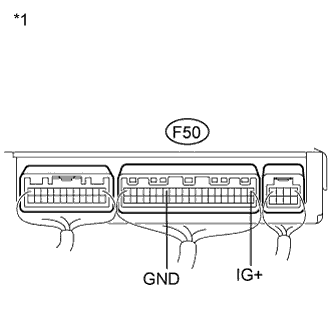
Text in Illustration *1 Component with harness connected
(A/C Amplifier)
Remove the A/C amplifier with the connectors still connected.
-
Measure the voltage according to the value(s) in the table below.
Standard Voltage Tester Connection Condition Specified Condition F50-1 (IG+) - F50-14 (GND) Power switch off Below 1 V F50-1 (IG+) - F50-14 (GND) Power switch on (IG) 11 to 14 V
NG 
CHECK HARNESS AND CONNECTOR (A/C AMPLIFIER - BATTERY) Click here
OK 
PROCEED TO NEXT SUSPECTED AREA SHOWN IN PROBLEM SYMPTOMS TABLE Click here
-
-
CHECK HARNESS AND CONNECTOR (A/C AMPLIFIER - BATTERY)
-
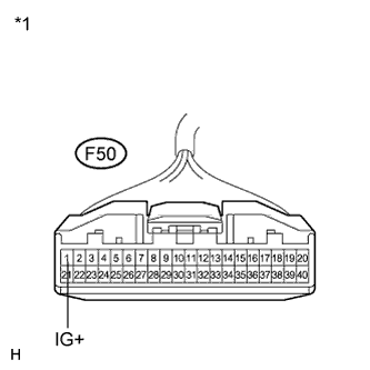
Text in Illustration *1 Front view of wire harness connector
(to A/C Amplifier)
Disconnect the A/C amplifier connector.
-
Measure the voltage according to the value(s) in the table below.
Standard Voltage Tester Connection Condition Specified Condition F50-1 (IG+) - Body ground Power switch off Below 1 V F50-1 (IG+) - Body ground Power switch on (IG) 11 to 14 V
NG 
REPAIR OR REPLACE HARNESS OR CONNECTOR
OK 
-
-
CHECK HARNESS AND CONNECTOR (A/C AMPLIFIER - BODY GROUND)
-
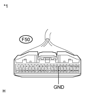
Text in Illustration *1 Front view of wire harness connector
(to A/C Amplifier)
Measure the resistance according to the value(s) in the table below.
Standard Resistance Tester Connection Condition Specified Condition F50-14 (GND) - Body ground Always Below 1 Ω
NG
REPAIR OR REPLACE HARNESS OR CONNECTOR
OK
REPLACE A/C AMPLIFIER Click here
-