AIR CONDITIONING SYSTEM Heater Water Pump Circuit
DESCRIPTION
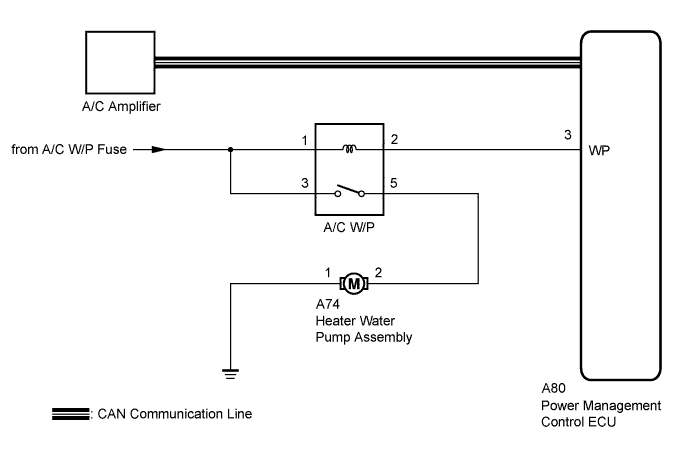
The heater water pump assembly sends engine coolant to the heater core assembly while the engine is stopped to prevent heater effectiveness from becoming low. Directed by the A/C amplifier, the power management control ECU operates the water pump relay and drives the heater water pump assembly.
WIRING DIAGRAM
INSPECTION PROCEDURE
Note
Inspect the fuses for circuits related to this system before performing the following inspection procedure.
PROCEDURE
-
CHECK CAN COMMUNICATION SYSTEM
-
Using the intelligent tester to check if the CAN communication system is functioning normally.
Result Result Proceed to CAN DTC is not output A CAN DTC is output B
B 
GO TO CAN COMMUNICATION SYSTEM Click here
A 
-
-
PERFORM ACTIVE TEST USING INTELLIGENT TESTER
-
Connect the intelligent tester to the DLC3.
-
Turn the power switch on (IG).
-
Turn the intelligent tester on.
-
Enter the following menus: Body / Air Conditioner / Active Test.
-
Check the operation by referring to the table below.
Air Conditioner Tester Display Test Part Control Range Diagnostic Note Water Pump Water pump relay OFF, ON - OK Heater water pump assembly operates smoothly.
NG 
INSPECT RELAY (A/C W/P) Click here
OK 
PROCEED TO NEXT SUSPECTED AREA SHOWN IN PROBLEM SYMPTOMS TABLE Click here
-
-
INSPECT RELAY (A/C W/P)
-
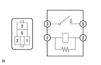
Remove the A/C W/P relay from the HV SUB relay block and junction block 2.
-
Measure the resistance according to the value(s) in the table below.
Standard Resistance Tester Connection Specified Condition 3 - 5 10 kΩ or higher 3 - 5 Below 1 Ω
(When battery voltage is applied between terminals 1 and 2)
NG
REPLACE RELAY (A/C W/P)
OK
-
-
CHECK HARNESS AND CONNECTOR (POWER MANAGEMENT CONTROL ECU - BATTERY)
-
Reinstall the A/C W/P relay to the HV SUB relay block and junction block 2.
-
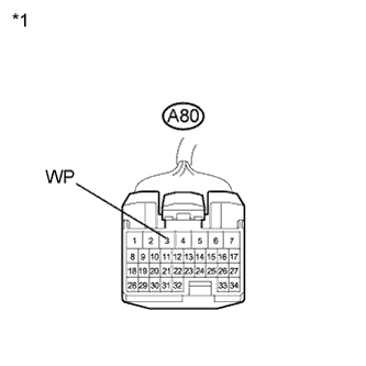
Text in Illustration *1 Front view of wire harness connector
(to Power Management Control ECU)
Disconnect the connector from the power management control ECU.
-
Measure the voltage according to the value(s) in the table below.
Standard Voltage Tester Connection Condition Specified Condition A80-3 (WP) - Body ground Power switch off Below 1 V A80-3 (WP) - Body ground Power switch on (IG) 11 to 14 V
NG
REPAIR OR REPLACE HARNESS OR CONNECTOR
OK
-
-
CHECK HARNESS AND CONNECTOR (BATTERY - HV SUB RELAY BLOCK AND JUNCTION BLOCK 2)
-

Text in Illustration *1 Component without relay installed
(HV SUB Relay Block and Junction Block 2)
Remove the A/C W/P relay from the HV SUB relay block and junction block 2.
-
Measure the voltage according to the value(s) in the table below.
Standard Voltage Tester Connection Condition Specified Condition Relay block A/C W/P relay terminal 3 - Body ground Power switch on (IG) 11 to 14 V Relay block A/C W/P relay terminal 3 - Body ground Power switch off Below 1 V
NG
REPAIR OR REPLACE HARNESS OR CONNECTOR
OK
-
-
INSPECT HEATER WATER PUMP ASSEMBLY
-
Disconnect the connector from the heater water pump assembly.
-
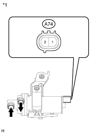
Text in Illustration *1 Component without harness connected
(Heater Water Pump Assembly)
Connect the positive (+) lead from a battery to terminal 2 and the negative (-) lead to terminal 1.
OK Heater water pump assembly operates smoothly. Note
Complete this inspection within 10 seconds if there is no water in the heater water pump assembly.
NG
REPLACE HEATER WATER PUMP ASSEMBLY Click here
OK
-
-
CHECK HARNESS AND CONNECTOR (HEATER WATER PUMP ASSEMBLY - BODY GROUND)
-
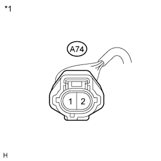
Text in Illustration *1 Front view of wire harness connector
(to Heater Water Pump Assembly)
Measure the resistance according to the value(s) in the table below.
Standard Resistance Tester Connection Condition Specified Condition A74-1 - Body ground Always Below 1 Ω
NG
REPAIR OR REPLACE HARNESS OR CONNECTOR
OK
-
-
CHECK HARNESS AND CONNECTOR (HEATER WATER PUMP ASSEMBLY - HV SUB R/B AND J/B 2)
-
Remove the A/C W/P relay from the HV SUB relay block and junction block 2.
-
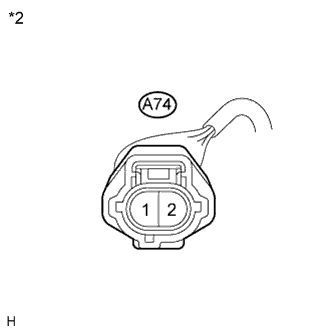
Text in Illustration *1 Component without relay installed
(HV SUB Relay Block and Junction Block 2)
*2 Front view of wire harness connector
(to Heater Water Pump Assembly)
Measure the resistance according to the value(s) in the table below.
Standard Resistance Tester Connection Condition Specified Condition A74-2 - Relay block A/C W/P relay terminal 5 Always Below 1 Ω A74-2 - Body ground Always 10 kΩ or higher
NG
REPAIR OR REPLACE HARNESS OR CONNECTOR
OK
-
-
REPLACE A/C AMPLIFIER
-
Replace the A/C amplifier with a normal one and check if the same problem occurs again Click here.
OK Same problem does not occur. Result Result Proceed to OK A NG
(for LHD)
B NG
(for RHD)
C
B
REPLACE POWER MANAGEMENT CONTROL ECU (for LHD) Click here
C
REPLACE POWER MANAGEMENT CONTROL ECU (for RHD) Click here
A
END (A/C AMPLIFIER WAS DEFECTIVE)
-