AIR CONDITIONING SYSTEM Air Conditioning Control Panel Circuit
DESCRIPTION
-
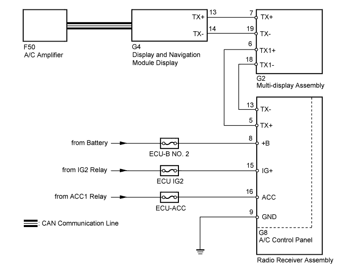
A/C control panel switch signals are sent to the display and navigation module display via AVC-LAN communication.
The display and navigation module display then sends these signals to the A/C amplifier via CAN communication.
w/ Navigation System:
-
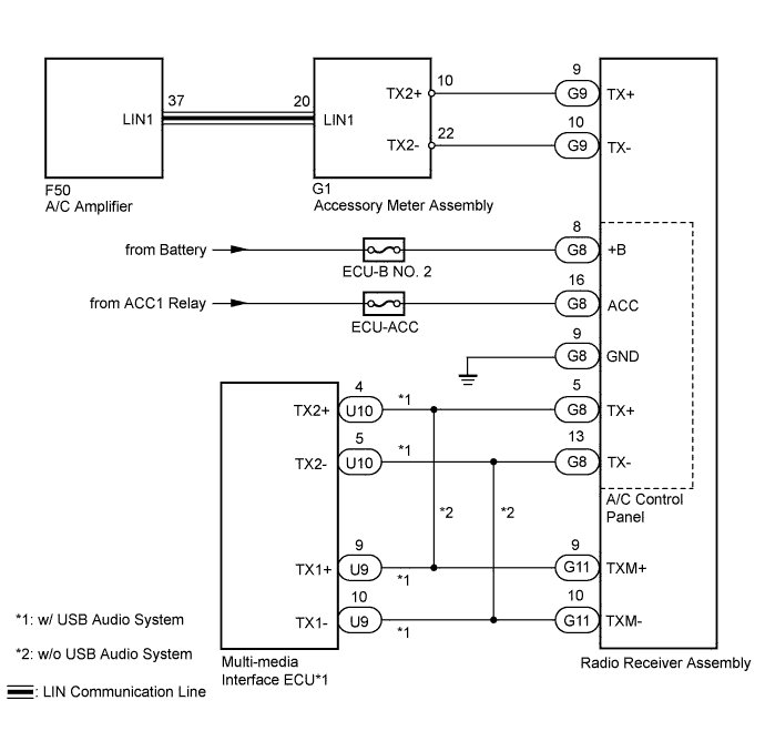
A/C control panel switch signals are sent to the accessory meter assembly via AVC-LAN communication.
The accessory meter assembly then sends these signals to the A/C amplifier via LIN communication.
w/o Navigation System:
WIRING DIAGRAM
-
w/ Navigation System
-
w/o Navigation System
INSPECTION PROCEDURE
Note
Inspect the fuses for circuits related to this system before performing the following inspection procedure.
PROCEDURE
-
CONFIRM MODEL
Result Result Proceed to w/ Navigation System A w/o Navigation System B
B 
CHECK AVC-LAN CIRCUIT Click here
A 
-
CHECK CAN COMMUNICATION SYSTEM
-
Use the intelligent tester to check if the CAN communication system is functioning normally.
Result Result Proceed to CAN DTC is not output A CAN DTC is output B
B 
GO TO CAN COMMUNICATION SYSTEM Click here
A
-
-
CHECK AVC-LAN CIRCUIT
-
Check for an open or short in all AVC-LAN circuits Click here for HDD, Click here for DVD).
OK There is no open or short circuit.
NG
REPAIR AVC-LAN CIRCUIT
OK
-
-
CHECK HARNESS AND CONNECTOR (POWER SOURCE, GROUND)
-
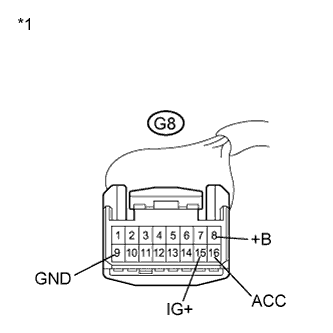
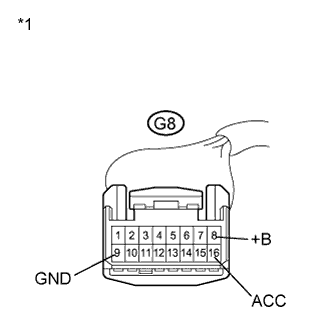
Text in Illustration *1 Front view of wire harness connector
(to A/C Control Panel)
Disconnect the A/C control panel connector.
-
Measure the voltage according to the value(s) in the table below.
Standard Voltage Tester Connection Condition Specified Condition G8-8 (+B) - Body ground Always 11 to 14 V G8-15 (IG+) - Body ground Power switch off Below 1 V G8-15 (IG+) - Body ground Power switch on (IG) 11 to 14 V G8-16 (ACC) - Body ground Power switch off Below 1 V G8-16 (ACC) - Body ground Power switch on (ACC) 11 to 14 V -
Measure the resistance according to the value(s) in the table below.
Standard Resistance Tester Connection Condition Specified Condition G8-9 (GND) - Body ground Always Below 1 Ω
NG
REPAIR OR REPLACE HARNESS OR CONNECTOR
OK 
PROCEED TO NEXT SUSPECTED AREA SHOWN IN PROBLEM SYMPTOMS TABLE Click here
-
-
CHECK AVC-LAN CIRCUIT
-
Check for an open or short in all AVC-LAN circuits Click here.
OK There is no open or short circuit.
NG
REPAIR AVC-LAN CIRCUIT
OK
-
-
CHECK HARNESS AND CONNECTOR (A/C AMPLIFIER - ACCESSORY METER ASSEMBLY)
-
Disconnect the A/C amplifier connector.
-
Disconnect the accessory meter assembly connector.
-
Measure the resistance according to the value(s) in the table below.
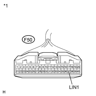
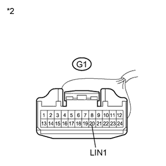
Standard Resistance Tester Connection Condition Specified Condition F50-37 (LIN1) - G1-20 (LIN1) Always Below 1 Ω F50-37 (LIN1) - Body ground Always 10 k Ω or higher Text in Illustration *1 Front view of wire harness connector
(to A/C Amplifier)
*2 Front view of wire harness connector
(to Accessory Meter Assembly)
NG
REPAIR OR REPLACE HARNESS OR CONNECTOR
OK
-
-
CHECK HARNESS AND CONNECTOR (POWER SOURCE, GROUND)
-
Text in Illustration *1 Front view of wire harness connector
(to A/C Control Panel)
Disconnect the A/C control panel connector.
-
Measure the voltage according to the value(s) in the table below.
Standard Voltage Tester Connection Condition Specified Condition G8-8 (+B) - Body ground Always Always 11 to 14 V G8-16 (ACC) - Body ground Power switch off Below 1 V G8-16 (ACC) - Body ground Power switch on (ACC) 11 to 14 V -
Measure the resistance according to the value(s) in the table below.
Standard Resistance Tester Connection Condition Specified Condition G8-9 (GND) - Body ground Always Below 1 Ω
NG
REPAIR OR REPLACE HARNESS OR CONNECTOR
OK
PROCEED TO NEXT SUSPECTED AREA SHOWN IN PROBLEM SYMPTOMS TABLE Click here
-