AIR CONDITIONING SYSTEM, Diagnostic DTC:B1476/76

| DTC Code | DTC Name |
|---|---|
| B1476/76 | A/C Inverter Load System Malfunction |
DESCRIPTION
The compressor with motor assembly stops compressor control and outputs this DTC if the rotation load is too large or too small while controlling motor rotation in the compressor with motor assembly.
Possible causes are refrigerant gas leakage, overcharged refrigerant gas, insufficient cooling because of a condenser fan circuit malfunction, or compressor lock.
| DTC No. | DTC Detection Condition | Trouble Area |
|---|---|---|
| B1476/76 | Motor rotation load while the compressor is operating is too large or too small. |
|
INSPECTION PROCEDURE
CAUTION:
-
Wear electrically insulated gloves and pull out the service plug grip before inspection as procedures may require disconnecting high-voltage connectors. Be sure to carry the removed service plug grip because other workers may install it by mistake.
-
Do not touch the high-voltage connectors or terminals for 10 minutes after the service plug grip is removed.
Note
The hybrid control system and air conditioning system output DTCs separately. Inspect DTCs following the flow chart for the hybrid control system first if any DTCs from those systems are output simultaneously.
PROCEDURE
-
CHECK CAN COMMUNICATION SYSTEM
-
Using the intelligent tester to check if the CAN communication system is functioning normally.
Result Result Proceed to CAN DTC is not output A CAN DTC is output B
B 
GO TO CAN COMMUNICATION SYSTEM Click here
A 
-
-
PERFORM ACTIVE TEST USING INTELLIGENT TESTER
-
Connect the intelligent tester to the DLC3.
-
Turn the power switch on (IG).
-
Turn the intelligent tester on.
-
Enter the following menus: Powertrain / Engine / Active Test.
-
Check the operation by referring to the table below.
Engine Tester Display Test Part Control Range Diagnostic Note Control the Electric Cooling Fan Electrical fan OFF, ON - OK Electrical fan operates smoothly.
NG
GO TO COOLING FAN SYSTEM Click here
OK
-
-
CHECK REFRIGERANT PRESSURE
-
Install the manifold gauge set Click here.
-
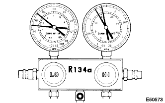
Read the manifold gauge pressure when the following conditions are established.
-
Prepare the vehicle according to the chart below.
Item Condition Vehicle Doors All fully open Compressor speed 5200 rpm Temperature Setting MAX COLD Blower Speed HI A/C switch ON R/F Switch RECIRCULATION
(30 to 35°C (86 to 95°F))
Standard Pressure Low pressure side 0.15 to 0.25 MPa (1.5 to 2.5 kgf/cm2, 21.3 to 35.6 psi) High pressure side 1.37 to 1.57 MPa (14 to 16 kgf/cm2, 199 to 228 psi)
-
NG
CHARGE REFRIGERANT Click here
OK 
REPLACE COMPRESSOR WITH MOTOR ASSEMBLY Click here
-