AIR CONDITIONING SYSTEM, Diagnostic DTC:B1462/62

| DTC Code | DTC Name |
|---|---|
| B1462/62 | Room Humidity Sensor Circuit |
DESCRIPTION
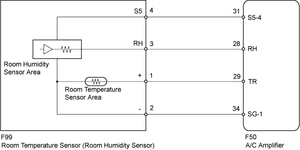
The room humidity sensor detects cabin humidity. The voltage of the room humidity sensor changes in accordance with cabin humidity. The A/C amplifier reads changes in the room humidity sensor.
The room humidity sensor is integrated with the room temperature sensor.
| DTC No. | DTC Detecting Condition | Trouble Area |
|---|---|---|
| B1462/62 | Open or short in room humidity sensor circuit |
|
WIRING DIAGRAM
INSPECTION PROCEDURE
PROCEDURE
-
READ VALUE USING INTELLIGENT TESTER
-
Connect the intelligent tester to the DLC3.
-
Turn the power switch on (IG).
-
Turn the intelligent tester on.
-
Enter the following menus: Body / Air Conditioner / Data List.
-
Check the value(s) by referring to the table below.
Air Conditioner Tester Display Measurement Item/Range Normal Condition Diagnostic Note Humidity Sensor Room humidity sensor / Min.: 0%, Max.: 100% Actual cabin humidity displayed - OK The display is as specified in the Normal Condition column. Result Result Proceed to NG A OK (When troubleshooting according to Problem Symptoms Table) B OK (When troubleshooting according to the DTC) C
B 
PROCEED TO NEXT SUSPECTED AREA SHOWN IN PROBLEM SYMPTOMS TABLE Click here
C
REPLACE A/C AMPLIFIER Click here
A 
-
-
CHECK HARNESS AND CONNECTOR (POWER SOURCE CIRCUIT)
-
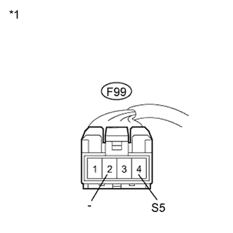
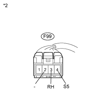
Text in Illustration *1 Front view of wire harness connector
(to Room Humidity Sensor)
Disconnect the room humidity sensor connector.
-
Measure the voltage according to the value(s) in the table below.
Standard Voltage Tester Connection Condition Specified Condition F99-4 (S5) - F99-2 (-) Power switch on (IG) 4.5 to 5.5 V
NG 
CHECK HARNESS AND CONNECTOR (ROOM HUMIDITY SENSOR - A/C AMPLIFIER) Click here
OK
-
-
INSPECT ROOM HUMIDITY SENSOR
-
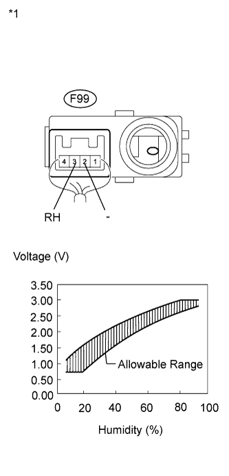
Text in Illustration *1 Component with harness connected
(Room Humidity Sensor)
Reconnect the room humidity sensor connector.
-
Turn the power switch on (IG).
-
Measure the voltage according to the value(s) in the table below.
Standard Voltage Tester Connection Condition Specified Condition F99-3 (RH) - F99-2 (-) at 25°C (77°F)
Humidity 10%
0.7 to 1.08 V F99-3 (RH) - F99-2 (-) at 25°C (77°F)
Humidity 20%
0.72 to 1.57 V F99-3 (RH) - F99-2 (-) at 25°C (77°F)
Humidity 30%
1.13 to 1.95 V F99-3 (RH) - F99-2 (-) at 25°C (77°F)
Humidity 40%
1.61 to 2.24 V F99-3 (RH) - F99-2 (-) at 25°C (77°F)
Humidity 50%
1.99 to 2.46 V F99-3 (RH) - F99-2 (-) at 25°C (77°F)
Humidity 60%
2.26 to 2.66 V F99-3 (RH) - F99-2 (-) at 25°C (77°F)
Humidity 70%
2.48 to 2.85 V F99-3 (RH) - F99-2 (-) at 25°C (77°F)
Humidity 80%
2.68 to 3.04 V F99-3 (RH) - F99-2 (-) at 25°C (77°F)
Humidity 90%
2.87 to 3.05 V Note
-
Do not touch the room humidity sensor because it may be affected by body temperature and may not work properly.
-
Hold the sensor only by its connector.
-
The output voltage at the ambient temperature 25°C (77°F) is shown above.
Tech Tips
As the humidity increases, the voltage increases (see the graph).
-
NG
REPLACE ROOM HUMIDITY SENSOR Click here
OK
-
-
CHECK HARNESS AND CONNECTOR (ROOM HUMIDITY SENSOR - A/C AMPLIFIER)
-
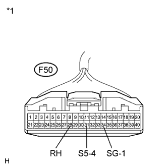
Disconnect the A/C amplifier connector.
-
Disconnect the room humidity sensor connector.
-
Measure the resistance according to the value(s) in the table below.
Standard Resistance Tester Connection Condition Specified Condition F50-31 (S5-4) - F99-4 (S5) Always Below 1 Ω F50-28 (RH) - F99-3 (RH) Always Below 1 Ω F50-34 (SG-1) - F99-2 (-) Always Below 1 Ω F50-31 (S5-4) - Body ground Always 10 kΩ or higher F50-28 (RH) - Body ground Always 10 kΩ or higher F50-34 (SG-1) - Body ground Always 10 kΩ or higher Text in Illustration *1 Front view of wire harness connector
(to A/C Amplifier)
*2 Front view of wire harness connector
(to Room Humidity Sensor)
NG
REPAIR OR REPLACE HARNESS OR CONNECTOR
OK 
REPLACE A/C AMPLIFIER Click here
-