AIR CONDITIONING SYSTEM, Diagnostic DTC:B1443/43

| DTC Code | DTC Name |
|---|---|
| B1443/43 | Air Outlet Damper Control Servo Motor Circuit |
DESCRIPTION
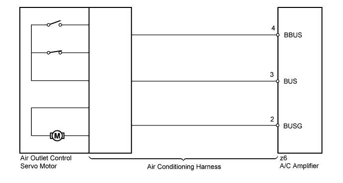
The air outlet control servo motor sends pulse signals to indicate the damper position to the A/C amplifier. The A/C amplifier activates the motor (normal or reverse) based on these signals to move the mode damper to any position, which controls the air outlet switching.
The A/C amplifier communicates with the servo through a communication/driver IC and wiring assembly called the air conditioning harness.
Tech Tips
Confirm that no mechanical problem is present because this DTC can be stored when either a damper link or the damper is mechanically locked.
| DTC No. | DTC Detection Condition | Trouble Area |
|---|---|---|
| B1443/43 | Air outlet damper position sensor value does not change even if A/C amplifier operates air outlet control servo motor |
|
WIRING DIAGRAM
INSPECTION PROCEDURE
PROCEDURE
-
READ VALUE USING INTELLIGENT TESTER
-
Connect the intelligent tester to the DLC3.
-
Turn the power switch on (IG).
-
Turn the intelligent tester on.
-
Operate the MODE switch.
-
Enter the following menus: Body / Air Conditioner / Data List.
-
Check the value(s) by referring to the table below.
Air Conditioner Tester Display Measurement Item/Range Normal Condition Diagnostic Note Air Outlet Servo Pulse (D) Air outlet servo motor target pulse / Min.: 0, Max.: 255 FACE: 8 (pulse)
B/L: 30 to 38 (pulse)
FOOT: 50 to 74 (pulse)
FOOT/DEF: 80 (pulse)
DEF: 97 (pulse)
- Air Outlet Servo Actu Pulse (D) Air outlet servo motor actual pulse / Min.: 0, Max.: 255 FACE: 8 (pulse)
B/L: 30 to 38 (pulse)
FOOT: 50 to 74 (pulse)
FOOT/DEF: 80 (pulse)
DEF: 97 (pulse)
- OK The display is as specified in the Normal Condition column. Result Result Proceed to NG A OK (When troubleshooting according to Problem Symptoms Table) B OK (When troubleshooting according to the DTC) C
B 
PROCEED TO NEXT SUSPECTED AREA SHOWN IN PROBLEM SYMPTOMS TABLE Click here
C
REPLACE A/C AMPLIFIER Click here
A 
-
-
PERFORM ACTIVE TEST USING INTELLIGENT TESTER
-
Connect the intelligent tester to the DLC3.
-
Turn the power switch on (IG).
-
Turn the intelligent tester on.
-
Enter the following menus: Body / Air Conditioner / Active Test.
-
Check the operation by referring to the table below.
Air Conditioner Tester Display Test Part Control Rage Diagnostic Note Air Outlet Servo Pulse (D) Air outlet servo motor pulse Min.: 0, Max.: 255 - OK Air flow position changes in accordance with each control range.
NG 
INSPECT AIR OUTLET CONTROL SERVO MOTOR Click here
OK 
REPLACE A/C AMPLIFIER Click here
-
-
INSPECT AIR OUTLET CONTROL SERVO MOTOR
-
Replace the air outlet control servo motor Click here.
Tech Tips
Since the servo motor cannot be inspected while it is removed from the vehicle, replace the servo motor with a new or a known good one and check that the condition returns to normal.
-
Check for the DTC.
Result Result Proceed to DTC B1443/43 is output A DTC B1443/43 is not output B
B
END (AIR OUTLET CONTROL SERVO MOTOR WAS DEFECTIVE)
A
-
-
INSPECT AIR CONDITIONING HARNESS
-
Replace the air conditioning harness Click here.
Tech Tips
Since the air conditioning harness cannot be inspected while it is removed from the vehicle, replace the air conditioning harness with a new or a known good one and check that the condition returns to normal.
-
Check for the DTC.
Result Result Proceed to DTC B1443/43 is output A DTC B1443/43 is not output B
B
END (AIR CONDITIONING HARNESS WAS DEFECTIVE)
A
REPLACE A/C AMPLIFIER Click here
-