AIR CONDITIONING SYSTEM, Diagnostic DTC:B1412/12

| DTC Code | DTC Name |
|---|---|
| B1412/12 | Ambient Temperature Sensor Circuit |
DESCRIPTION
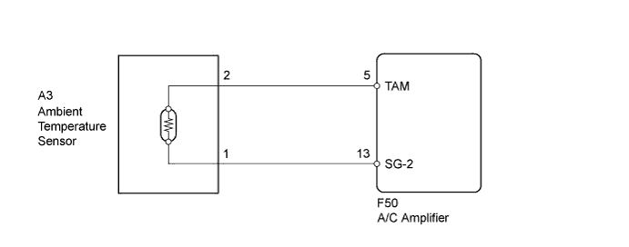
The ambient temperature sensor is installed in front of the condenser. It detects the ambient temperature to control air conditioning AUTO mode. This sensor is connected to the A/C amplifier and detects fluctuations in the ambient temperature. This data is used for controlling the cabin temperature. The sensor sends a signal to the A/C amplifier. The resistance of the ambient temperature sensor changes in accordance with the ambient temperature. As the temperature decreases, the resistance increases. As the temperature increases, the resistance decreases.
The A/C amplifier applies voltage (5 V) to the ambient temperature sensor and reads voltage changes as the resistance of the ambient temperature sensor changes.
| DTC No. | DTC Detection Condition | Trouble Area |
|---|---|---|
| B1412/12 | Open or short in ambient temperature sensor circuit |
|
WIRING DIAGRAM
INSPECTION PROCEDURE
PROCEDURE
-
READ VALUE USING INTELLIGENT TESTER
-
Connect the intelligent tester to the DLC3.
-
Turn the power switch on (IG).
-
Turn the intelligent tester on.
-
Enter the following menus: Body / Air Conditioner / Data List.
-
Check the value(s) by referring to the table below.
Air Conditioner Tester Display Measurement Item/Range Normal Condition Diagnostic Note Ambient Temp Sensor Ambient temperature sensor /
Min: -23.3°C (-9.94°F)
Max: 65.95°C (150.71°F)
Actual ambient temperature displayed - OK The display is as specified in the Normal Condition column. Result Result Proceed to NG A OK (When troubleshooting according to Problem Symptoms Table) B OK (When troubleshooting according to the DTC) C
B 
PROCEED TO NEXT SUSPECTED AREA SHOWN IN PROBLEM SYMPTOMS TABLE Click here
C
REPLACE A/C AMPLIFIER Click here
A 
-
-
INSPECT AMBIENT TEMPERATURE SENSOR
-
Remove the ambient temperature sensor.
-
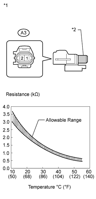
Text in Illustration *1 Component without harness connected
(Ambient Temperature Sensor)
*2 Sensing Portion Disconnect the ambient temperature sensor connector.
-
Measure the resistance according to the value(s) in the table below.
Standard Resistance Tester Connection Condition Specified Condition A3-1 - A3-2 10°C (50°F) 3.00 to 3.73 kΩ A3-1 - A3-2 15°C (59°F) 2.45 to 2.88 kΩ A3-1 - A3-2 20°C (68°F) 1.95 to 2.30 kΩ A3-1 - A3-2 25°C (77°F) 1.60 to 1.80 kΩ A3-1 - A3-2 30°C (86°F) 1.28 to 1.47 kΩ A3-1 - A3-2 35°C (95°F) 1.00 to 1.22 kΩ A3-1 - A3-2 40°C (104°F) 0.80 to 1.00 kΩ A3-1 - A3-2 45°C (113°F) 0.65 to 0.85 kΩ A3-1 - A3-2 50°C (122°F) 0.50 to 0.70 kΩ A3-1 - A3-2 55°C (131°F) 0.44 to 0.60 kΩ A3-1 - A3-2 60°C (140°F) 0.36 to 0.50 kΩ Note
-
Hold the sensor only by its connector. Touching the sensor may change the resistance value.
-
When measuring, the sensor temperature must be the same as the ambient temperature.
Tech Tips
As the temperature increases, the resistance decreases (see the graph).
-
NG
REPLACE AMBIENT TEMPERATURE SENSOR Click here
OK
-
-
CHECK HARNESS AND CONNECTOR (AMBIENT TEMPERATURE SENSOR - A/C AMPLIFIER)
-
Disconnect the A/C amplifier connector.
-
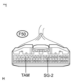
Text in Illustration *1 Front view of wire harness connector
(to A/C Amplifier)
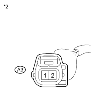
*2 Front view of wire harness connector
(to Ambient Temperature Sensor)
Measure the resistance according to the value(s) in the table below.
Standard Resistance Tester Connection Condition Specified Condition F50-5 (TAM) - A3-2 Always Below 1 Ω F50-13 (SG-2) - A3-1 Always Below 1 Ω F50-5 (TAM) - Body ground Always 10 kΩ or higher F50-13 (SG-2) - Body ground Always 10 kΩ or higher
NG
REPAIR OR REPLACE HARNESS OR CONNECTOR
OK 
REPLACE A/C AMPLIFIER Click here
-