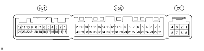
AIR CONDITIONING SYSTEM TERMINALS OF ECU

-
A/C AMPLIFIER
Tech Tips
Check from the rear of the connector while it is connected to the A/C amplifier.
Terminal No.
(Symbol)
Wiring Color Terminal Description Condition Specified Condition F50-1 (IG+) - F50-14 (GND) P - W-B Power source (IG) Power switch on (IG) 11 to 14 V F50-1 (IG+) - F50-14 (GND) P - W-B Power source (IG) Power switch off Below 1 V F50-5 (TAM) - F50-13 (SG-2) V - LG Ambient temperature sensor signal Power switch on (IG)
Ambient temperature: 25°C (77°F)
1.35 to 1.75 V F50-5 (TAM) - F50-13 (SG-2) V - LG Ambient temperature sensor signal Power switch on (IG)
Ambient temperature: 40°C (104°F)
0.9 to 1.2 V F50-6 (DGS) - F50-13 (SG-2)*1 SB - LG Smog ventilation sensor signal (HC, CO) After 30 seconds from power switch on (IG) and sensor exposed to exhaust gas (HC, CO) 1.0 to 4.5 V F50-9 (PRE) - F50-13 (SG-2) W - LG A/C pressure sensor signal Engine is running, A/C system is operating, Refrigerant pressure: Abnormal pressure (more than 3140 kPa (32.0 kgf/cm2, 455 psi))
4.84 V or higher F50-9 (PRE) - F50-13 (SG-2) W - LG A/C pressure sensor signal Engine is running, A/C system is operating, Refrigerant pressure: Abnormal pressure (less than 196 kPa (2.0 kgf/cm2, 28 psi))
Below 0.73 V F50-9 (PRE) - F50-13 (SG-2) W - LG A/C pressure sensor signal Engine is running, A/C system is operating, Refrigerant pressure: Normal pressure (less than 3140 kPa (32.0 kgf/cm2, 455 psi) and more than 196 kPa (2.0 kgf/cm2, 28 psi))
0.73 to 4.84 V F50-10 (S5-3) - F50-13 (SG-2) P - LG Power supply for A/C pressure sensor Power switch on (IG)
A/C switch: on
4.75 to 5.25 V F50-10 (S5-3) - F50-13 (SG-2) P - LG Power supply for A/C pressure sensor Power switch on (IG)
A/C switch: off
Below 1 V F50-11 (CANH) - F50-12 (CANL) B - W CAN communication system CAN communication circuit Pulse generation F50-13 (SG-2) - Body ground LG - Body ground Ground for A/C pressure sensor, A/C ambient temperature sensor, smog ventilation sensor Always Below 1 V F50-14 (GND) - Body ground W-B - Body ground Ground for main power supply Always Below 1 V F50-21 (B) - F50-14 (GND) G - W-B Power source (Back-up) Always 11 to 14 V F50-23 (BLW) - F50-14 (GND) L - W-B Blower motor speed control signal Power switch on (IG)
Blower switch: LO
Pulse generation
(See waveform 1)
F50-28 (RH) - F50-34 (SG-1) Y - V Room humidity sensor signal Power switch on (IG)
Cabin humidity: 40%
1.61 to 2.24 V F50-28 (RH) - F50-34 (SG-1) Y - V Room humidity sensor signal Power switch on (IG)
Cabin humidity: 60%
2.26 to 2.66 V F50-29 (TR) - F50-34 (SG-1) BE - V Room temperature sensor signal Power switch on (IG)
Cabin temperature: 25°C (77°F)
1.8 to 2.2 V F50-29 (TR) - F50-34 (SG-1) BE - V Room temperature sensor signal Power switch on (IG)
Cabin temperature: 40°C (104°F)
1.2 to 1.6 V F50-31 (S5-4) - F50-34 (SG-1) L - V Power supply for room temperature sensor, room humidity sensor Power switch off Below 1 V F50-31 (S5-4) - F50-34 (SG-1) L - V Power supply for room temperature sensor, room humidity sensor Power switch on (IG) 4.5 to 5.5 V F50-32 (TSP) - F50-14 (GND) Y - W-B*3
R - W-B*4
Solar sensor signal (for Front passenger side) Power switch on (IG)
Solar sensor subjected to electric light
0.8 to 4.3 V F50-32 (TSP) - F50-14 (GND) Y - W-B*3
R - W-B*4
Solar sensor signal (for Front passenger side) Power switch on (IG)
Solar sensor covered with a cloth
Below 0.8 V F50-33 (TSD) - F50-14 (GND) R - W-B*3
Y - W-B*4
Solar sensor signal (for Driver side) Power switch on (IG)
Solar sensor subjected to electric light
0.8 to 4.3 V F50-33 (TSD) - F50-14 (GND) R - W-B*3
Y - W-B*4
Solar sensor signal (for Driver side) Power switch on (IG)
Solar sensor covered with a cloth
Below 0.8 V F50-34 (SG-1) - Body ground V - Body ground Ground for room temperature sensor, room humidity sensor Always Below 1 V F50-37 (LIN1) - F50-14 (GND)*2 SB - W-B LIN communication signal Power switch on (IG) Pulse generation F51-3 (DGS1) - F50-14 (GND)*1 B - W-B Smog ventilation sensor signal (NOx) After 30 seconds from power switch on (IG) and sensor exposed to exhaust gas (NOx) 1.0 to 4.5 V z6-2 (BUSG) - Body ground - Ground for BUS IC Always Below 1 V z6-3 (BUS) - z6-2 (BUSG) - BUS IC control signal Power switch on (IG) Pulse generation z6-4 (BBUS) - z6-2 (BUSG) - Power supply for BUS IC Power switch off Below 1 V z6-4 (BBUS) - z6-2 (BUSG) - Power supply for BUS IC Power switch on (IG) 11 to 14 V z6-5 (SG) - Body ground - Ground for evaporator temperature sensor Always Below 1 V z6-6 (TE) - z6-5 (SG) - A/C evaporator temperature sensor signal Power switch on (IG)
Evaporator temperature: 0°C (32°F)
1.7 to 2.1 V z6-6 (TE) - z6-5 (SG) - A/C evaporator temperature sensor signal Power switch on (IG)
Evaporator temperature: 15°C (59°F)
0.9 to 1.3 V
-
*1: w/ Navigation System
-
*2: w/o Navigation System
-
*3: for LHD
-
*4: for RHD
-
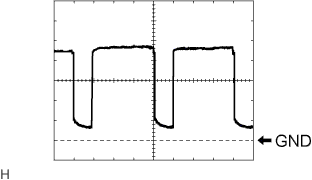
Waveform 1:
Item Content Terminal No. F50-23 (BLW) - F50-14 (GND) Tool Setting 1 V/DIV., 500 μs/DIV. Vehicle Condition Power switch on (IG)
Blower switch: LO
-
-
RADIO RECEIVER ASSEMBLY (A/C CONTROL PANEL)

Tech Tips
Check from the rear of the connector while it is connected to the radio receiver assembly (A/C control panel).
Terminal No.
(Symbol)
Wiring Color Terminal Description Condition Specified Condition G8-5 (TX+) Y AVC-LAN communication signal - - G8-8 (+B) - G8-9 (GND) SB - BR Power source (Back-up) Always 11 to 14 V G8-9 (GND) - Body ground BR - Body ground Ground for radio receiver (A/C control panel) Always Below 1 V G8-13 (TX-) W AVC-LAN communication signal - - G8-15 (IG+) - G8-9 (GND) Y - BR Power source (IG) Power switch off Below 1 V G8-15 (IG+) - G8-9 (GND) Y - BR Power source (IG) Power switch on (IG) 11 to 14 V G8-16 (ACC) - G8-9 (GND) GR - BR Power source (ACC) Power switch off Below 1 V G8-16 (ACC) - G8-9 (GND) GR - BR Power source (ACC) Power switch on (ACC) 11 to 14 V -
ACCESSORY METER ASSEMBLY (w/o Navigation System)

Tech Tips
Check from the rear of the connector while it is connected to the accessory meter assembly.
Terminal No.
(Symbol)
Wiring Color Terminal Description Condition Specified Condition G1-1 (IG+) - G1-12 (GND1) V - W-B Power source (IG) Power switch off Below 1 V G1-1 (IG+) - G1-12 (GND1) V - W-B Power source (IG) Power switch on (IG) 11 to 14 V G1-2 (IG2) - G1-12 (GND1) LG - W-B Power source (IG) Power switch off Below 1 V G1-2 (IG2) - G1-12 (GND1) LG - W-B Power source (IG) Power switch on (IG) 11 to 14 V G1-3 (ACC) - G1-12 (GND1) W - W-B Power source (ACC) Power switch off Below 1 V G1-3 (ACC) - G1-12 (GND1) W - W-B Power source (ACC) Power switch on (ACC) 11 to 14 V G1-10 (TX2+) P AVC-LAN communication signal - - G1-12 (GND1) - Body ground W-B - Body ground Ground for accessory meter assembly Always Below 1 V G1-13 (+B) - G1-12 (GND1) GR - W-B Power source (Back-up) Always 11 to 14 V G1-20 (LIN1) - G1-12 (GND1) SB - W-B LIN communication signal Power switch on (IG) Pulse generation G1-22 (TX2-) L AVC-LAN communication signal - - -
POWER MANAGEMENT CONTROL ECU Click here
-
MULTI-DISPLAY ASSEMBLY (w/ Navigation System (for DVD)) Click here
-
MULTI-DISPLAY ASSEMBLY (w/ Navigation System (for HDD)) Click here